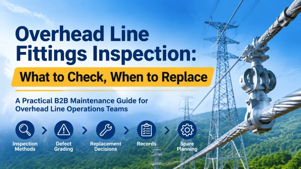
Проверка комплектующих воздушных линий электропередачи: что проверять и когда заменять
Overhead line fittings inspection is most useful when it does more than produce photographs. A good patrol separates harmless appearance changes from defects that can release a conductor, create a high-resistance joint, damage strands, or allow vibration to spread. It also tells the maintenance planner what needs immediate replacement, what can enter a planned outage, and what should be photographed again under comparable conditions.
This guide presents a whole-line method for operations and maintenance teams. It covers patrol triggers, observation tools, fitting-specific symptoms, replacement decisions, records, and spare stock. It does not assign universal wear limits, torque values, or inspection intervals. Those decisions must follow the project maintenance procedure, conductor data, fitting drawing, manufacturer specification sheet, loading condition, and the consequence of failure at the location.
Build the Inspection Program Around Risk and Evidence
Scheduled patrols provide the baseline. Their frequency should come from the utility or project procedure, then be adjusted for line criticality, environment, defect history, access, conductor loading, and failure consequence. The route sheet should identify structures that deserve extra attention: dead ends, large angles, crossings, long spans, exposed ridges, coastal or industrial zones, and locations with recurring vibration or contamination.
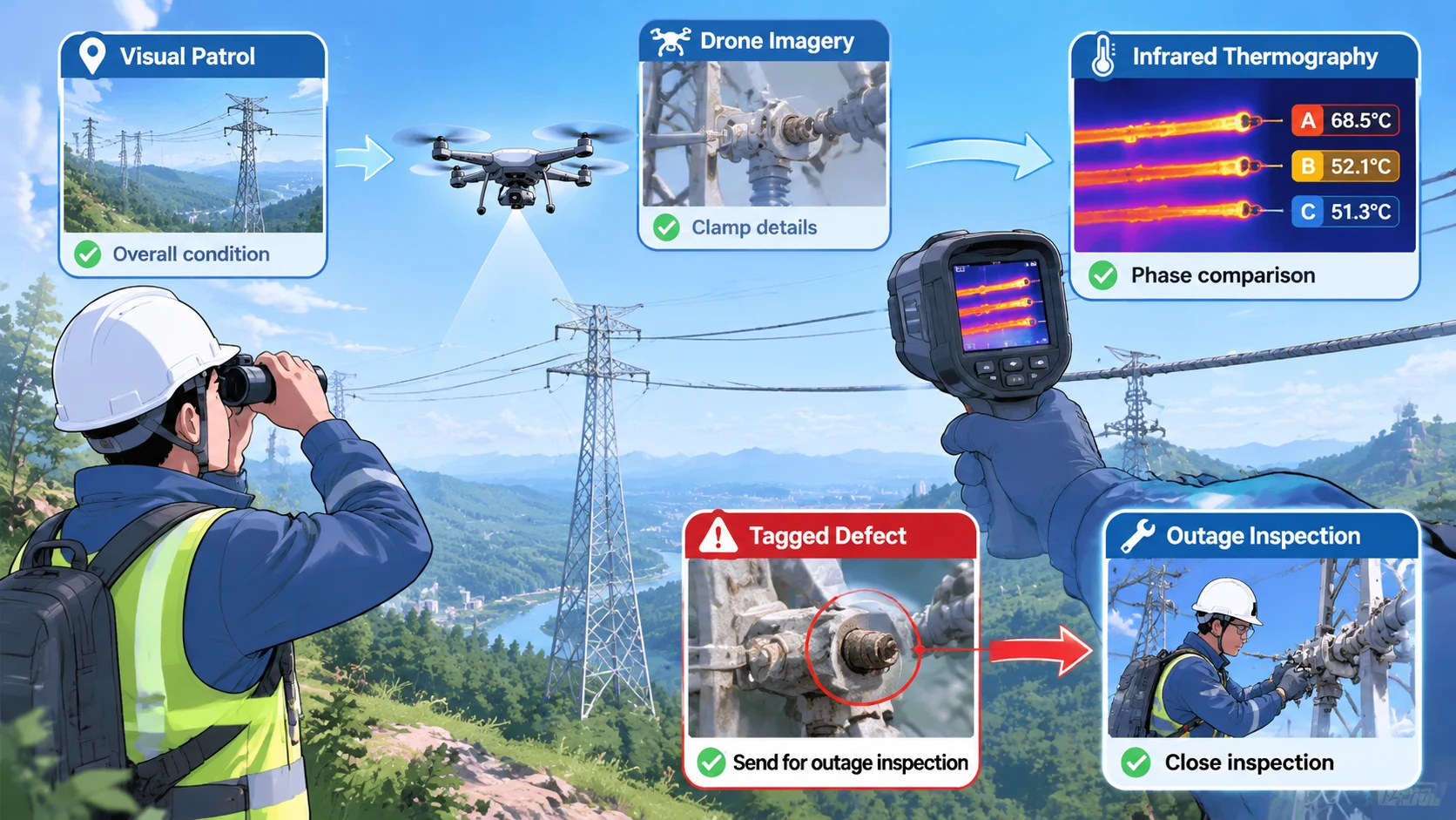
Do not make every patrol identical. A ground patrol is efficient for missing hardware, displaced components, abnormal sag, corrosion, and obvious conductor damage. A night patrol can reveal glow, intermittent arcing, or corona-like activity that daylight hides. Infrared work can screen current-carrying connectors for abnormal thermal patterns. A drone or long-range camera provides views of clamp mouths, upper surfaces, retaining parts, and bundled-conductor hardware that are difficult to see from the ground.
Special patrols should be event-driven. Dispatch an inspection after severe wind, galloping, heavy ice or sudden ice shedding, lightning activity, wildfire or intense heat exposure, flooding or slope movement near structures, and nearby construction that could strike conductors or foundations. Also trigger a focused inspection after reports of line noise, visible sparking, repeated protection operations, local overheating, unusual radio interference, or a change in sag. The inspection scope should follow the expected damage mechanism rather than reuse a generic checklist.
Before entering the route, review earlier photographs, defect tickets, load history, completed work, and the component map. For a broader refresher on how conductors, insulators, fittings, dampers, and structures interact, use this overhead power line and components guide. The aim is to compare each assembly with its own previous condition and with equivalent hardware on adjacent phases, not with an idealized catalog photograph.
Choose the Tool by the Question You Need to Answer
Unaided visual inspection can find missing pins or nuts, detached dampers, displaced spacers, gross corrosion, burned polymer housings, broken conductor strands, foreign objects, abnormal jumper position, and a clamp that has moved relative to a reference mark. It can also identify secondary evidence such as dark deposits, melted grease, rust streaks, or shiny fretting marks. It cannot confirm internal wear, remaining mechanical strength, hidden water entry, correct bolt preload, or the quality of a completed compression joint.
Binoculars, a spotting scope, and telephoto photography improve identification of locking devices, cotter pins, U-bolt thread engagement, keeper alignment, wedge position, armour-rod ends, strand condition near a clamp mouth, and marks that show movement. Capture an overview and a close view from repeatable angles. Scale, structure number, phase, circuit side, and image direction make the photographs useful later.
Drone imagery adds viewing angles rather than certainty. It is effective for upper surfaces, the back of fittings, spacer position, missing hardware, conductor contact points, and remote spans. Glare, shadow, motion blur, vegetation, and perspective can imitate cracks or displacement. A trained reviewer should compare the images with drawings and previous flights before assigning a defect grade.
Infrared thermography answers a narrower question: is a current-carrying connection behaving thermally differently from comparable phases or neighboring fittings under similar load and exposure? Record circuit load, weather, wind, viewing angle, emissivity assumptions, and the comparison point. A hot connection can indicate poor contact, oxidation, contamination, incorrect installation, or conductor damage. A cool image does not prove a joint is sound when load is low or wind is strong.
De-energized close inspection is required when the decision depends on what remote methods cannot establish. Examples include checking conductor strands beneath a clamp or armour rods, confirming hidden corrosion and water paths, cleaning a connection for assessment, verifying wedge seating and conductor marking, checking bolt condition with the approved procedure, or removing a suspect fitting for dimensional or laboratory examination. Energized-line methods may be available to qualified organizations, but the applicable work method, clearances, tools, and authorization must control the task.
Component-by-Component Inspection and Replacement Criteria
Judge each fitting as part of an assembly. A loose bolt may be the final symptom of vibration, a wrong conductor range, a deformed keeper, or repeated thermal cycling. Replacing the visible part without checking the conductor and connected hardware can return the same defect to service.
Suspension Clamps
From the ground or a drone, check whether the clamp body has shifted, rotated, or become asymmetric relative to the insulator string and conductor. Look for movement against paint marks or known reference points, a changed conductor exit angle, loose or displaced armour rods, uneven keeper seating, missing locking parts, and U-bolts or nuts that no longer match the adjacent assembly. Examine the conductor near both clamp mouths for polished areas, flattened strands, birdcaging, broken strands, and dark debris associated with fretting.
Displacement with no conductor damage may justify a planned close inspection, but unexplained continued movement, loose load-bearing hardware, visible strand damage, severe deformation, or loss of conductor support requires urgent isolation and replacement under the project procedure. Tightening a loose U-bolt is not automatically a repair: first determine whether the bolt, nut, keeper, clamp body, conductor, and anti-vibration system remain fit for reuse. For detailed symptom-to-cause diagnosis, refer to the dedicated suspension clamp failure field checks rather than duplicating that process here. Installation history can also be compared with the Руководство по установке подвесного зажима.
Tension Clamps and Dead-End Assemblies
At a compression dead end, scan the sleeve and connected jumper hardware for an abnormal thermal pattern. Visually check for sleeve movement, distortion, split surfaces, irregular crimp geometry, conductor strand disturbance, and corrosion around the steel anchor or attachment. Remote inspection cannot certify the internal quality of a compression joint; installation records, die and press records, electrical behavior, and any approved follow-up test matter.
For wedge types, compare wedge position and conductor marks with installation references. A wedge that has backed out, a conductor that has slipped, new sag, housing damage, or jacket and strand injury is not corrected by simply driving the same wedge back into place unless the approved instruction explicitly permits it after a complete assessment. For bolted types, check hardware retention, keeper alignment, body deformation, corrosion, and evidence of movement.
Severe steel-anchor corrosion, cracked or deformed load-path parts, confirmed slip, strand damage at a dead end, or significant thermal damage calls for replacement and an assembly-level investigation. Use the suspension clamp versus tension clamp comparison to keep support and termination roles distinct, and the tension clamp types comparison when identifying family-specific failure evidence.
Insulation-Piercing Connectors
Inspect the polymer shell for carbonization, melting, cracks, UV degradation, tracking marks, and gaps that could admit water. Confirm that the branch conductor is supported and has not pulled down on the connector. Look for corrosion products or moisture staining at cable entries. The expected condition of a shear-head fastener must be interpreted using the installation instructions: an intact head may indicate an incomplete installation, while an absent head alone does not prove the electrical contact remains sound.
Carbonization, melting, active arcing evidence, a loose branch, visible water entry with electrical deterioration, or damage to the main conductor requires prompt replacement using an approved work method. Do not reuse a piercing connector unless its manufacturer explicitly allows it. Compare the observed assembly with the steps in this insulation-piercing connector installation guide, including conductor support and sealing details.
Parallel-Groove Clamps and Splice Sleeves
These current-carrying joints deserve visual and infrared comparison under meaningful load. Look for abnormal heating, oxidation, corrosion products, darkened metal, damaged inhibitor seals, uneven clamp halves, loose locking hardware, and conductor strands extruding from the groove. On splice sleeves, check for movement marks, distorted or irregular compression areas, strand damage at each sleeve end, and a thermal difference from the continuous conductor.
A repeated hot pattern, thermal damage, evidence of conductor movement, severe oxidation at the contact interface, cracked hardware, or damaged strands normally moves the joint toward replacement rather than retightening. Bolt relaxation should prompt a search for contamination, wrong conductor range, incompatible materials, poor surface preparation, vibration, and previous overheating. The product geometry and application distinctions are summarized on the parallel-groove clamp page.
Armour Rods and Preformed Fittings
Check for broken rods, a set that has moved away from its reference position, rods ending at inconsistent locations, crossed or missing elements, and individual rod ends standing proud of the conductor. Inspect the conductor where the rods finish because an abrupt contact point can concentrate bending. Also look for polishing, corrosion, foreign material, and evidence that the set was applied to the wrong cable diameter or has been disturbed after loading.
A broken element, confirmed set movement, exposed conductor injury, widespread rod lift, or a mismatch with the cable identification requires close assessment and usually replacement of the complete set according to manufacturer instructions. Do not press a single raised rod back into service as a cosmetic correction. Preformed products work as matched assemblies, so mixing old and new rods can change load distribution.
Vibration Dampers, Spacer-Dampers, and Spacers
Check damper location against installation references, attachment security, messenger-wire condition, missing weights, deformation, corrosion, and marks showing the clamp has migrated. For bundled conductors, compare spacer position, frame alignment, elastomer condition, hinges, bolts, and the distance and orientation between subconductors. Look for collision marks, conductor polishing, local strand damage, and an altered bundle shape.
A detached or displaced device can expose the conductor to continuing vibration before obvious strand failure appears. Missing parts, cracked frames, failed hinges, severe elastomer damage, conductor contact, or inability to retain the specified geometry should be scheduled according to line risk, with immediate action where the device or loose part could fall, strike another phase, or allow active conductor damage.
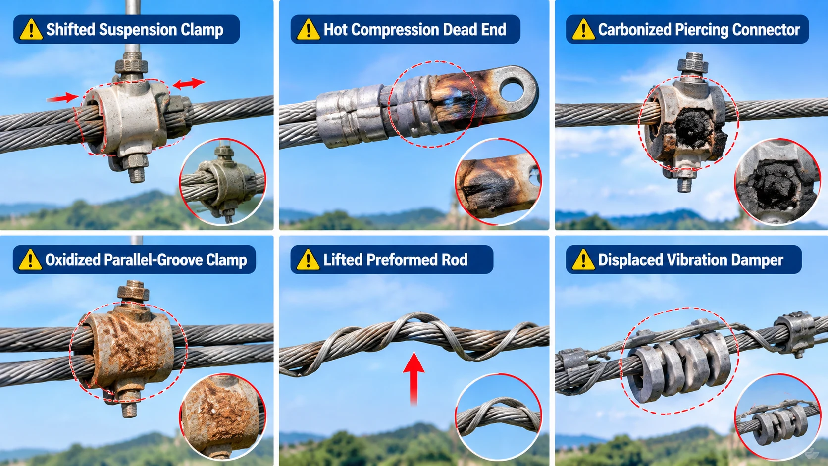
Turn Observations Into a Consistent Action Grade
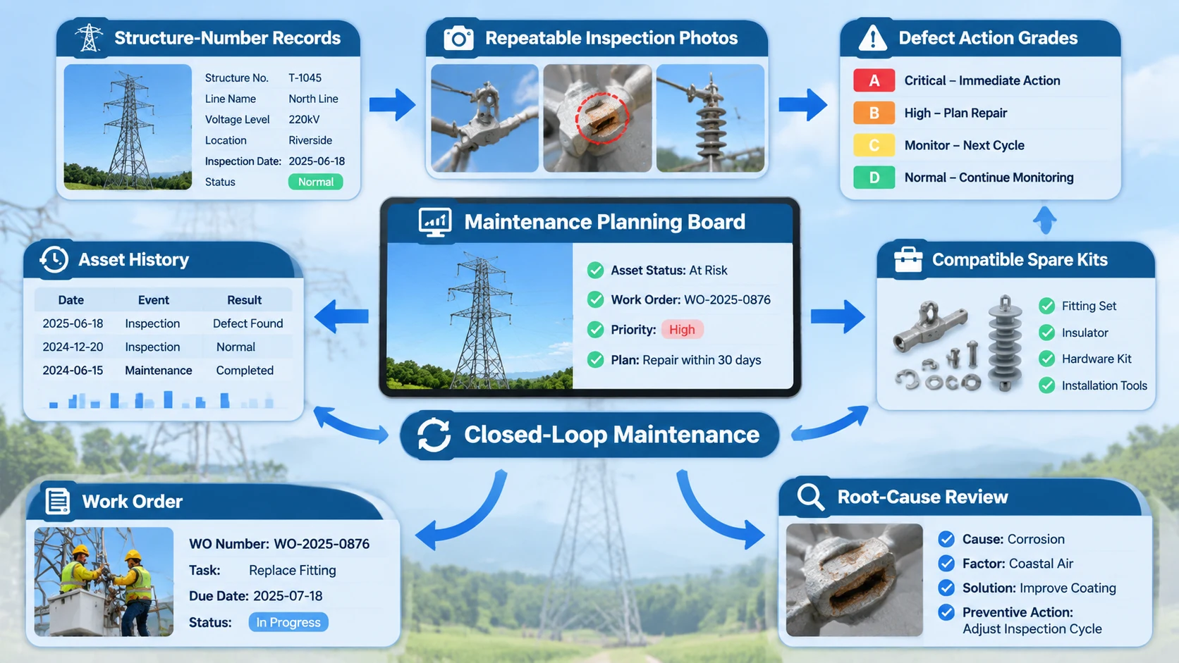
Use three action grades only after applying local safety and engineering rules. Replace immediately means the observed condition threatens the mechanical load path, conductor integrity, electrical contact, required clearance, or public safety and cannot wait for normal planning. Plan corrective work means deterioration is real but stable enough for a controlled outage or approved maintenance window. Continue observation means no functional deterioration is confirmed, evidence is incomplete, or the change is superficial; define what will be compared next time.
The table is a qualitative field aid, not a substitute for the project defect standard. If the project procedure assigns a stricter grade, the stricter decision controls.
| Observed condition | Possible cause | Replace immediately | Plan corrective work | Continue observation |
|---|---|---|---|---|
| Clamp or conductor has clearly slipped and clearance or load transfer is affected | Loss of grip, wrong size, poor installation, overload, or damaged conductor | Yes; secure the risk and replace the affected assembly | Нет | Нет |
| Abnormal heating with discoloration, melting, arcing evidence, or damaged strands | High contact resistance, oxidation, contamination, loose joint, or conductor injury | Yes, subject to the approved switching and work plan | Нет | Нет |
| Repeatable thermal difference without visible damage | Developing contact resistance or unequal load | If escalation or risk assessment requires it | Confirm load context and arrange close inspection | Only with a defined recheck and comparable load |
| Broken strands, birdcaging, severe flattening, or active fretting at a clamp mouth | Vibration, over-tightening, wrong groove, movement, or bending concentration | Yes when conductor integrity is compromised | For minor evidence only when the project procedure permits | No unexplained strand damage should be left undocumented |
| Loose or missing load-bearing fastener, pin, or retaining device | Vibration, installation error, corrosion, or previous disturbance | Yes when loss of support or detachment is credible | Yes when redundancy and procedure allow controlled repair | Нет |
| Carbonized or cracked polymer connector housing with moisture path | Overheating, arcing, UV degradation, impact, or failed sealing | Yes when electrical deterioration is present | Yes for confirmed enclosure damage without active heating | Only for superficial marks proven stable |
| Surface corrosion with coating loss but no section loss or deformation confirmed | Environment, damaged coating, or dissimilar-metal exposure | Only if load-path integrity is uncertain | Clean, assess, protect, or replace per procedure | Yes with repeatable photographs if judged superficial |
| Damper or spacer has moved, loosened, or lost a part | Vibration, incorrect installation, impact, or material degradation | When a loose part or conductor contact creates immediate risk | Yes; restore the complete vibration-control system | Only if position is within approved installation references |
| Single preformed rod end is raised with no confirmed movement or strand injury | Installation irregularity, impact, or developing set displacement | If close inspection finds breakage or conductor damage | Inspect the complete matched set during an approved outage | Photograph and trend only if the approved procedure allows |
Record Enough Detail to Make the Next Decision Better
Every finding should be tied to a structure number, circuit, phase, side of structure, fitting function, and conductor or cable. Record the fitting family, visible identification, installation position, observation method, weather, circuit loading when relevant, image numbers, defect description, action grade, responsible reviewer, and required completion or review point. Avoid entries such as “clamp rusty” without location, extent, comparison, or photograph.
Keep an asset history by pole or tower number. Link installation records, previous patrols, infrared images, drone images, work orders, replacement parts, and removed-component findings. Use the same photo viewpoint when practical. Trending makes slow movement, corrosion growth, recurring hot spots, and repeated defects in one design, batch, crew practice, or environmental zone visible.
When a fitting is replaced, close the loop. Record the removed condition, likely cause, conductor condition beneath it, mating hardware condition, replacement make and model, compatibility check, installation records, and post-work verification. If the defect repeats, escalate from component replacement to an engineering review of vibration, loading, materials, drainage, conductor range, and work practice.
Keep Spares for Restoration, Not Just Inventory Counts
A practical line-hardware stock should cover the fittings whose absence would extend an outage: suspension clamp sets, compatible armour rods, the relevant dead-end families, approved connectors, parallel-groove clamps or project-specific joints, vibration dampers, spacers or spacer-dampers, U-bolts and locking hardware, shackles, clevises, pins, and cotters. Include installation consumables and approved sealing or joint compounds where the product instruction requires them.
Stock by actual conductor and cable designation, not by generic appearance. Preformed sets, wedges, grooves, compression sleeves, and dies can look similar while being incompatible. Label complete kits, protect them from contamination and corrosion, and link shelf identity to the drawing and specification sheet. Keep any required tools, dies, gauges, and calibration status available with the part.
Set spare margin from criticality, lead time, route exposure, installed population, common failure modes, and restoration strategy. Use project inventory policy rather than an invented universal percentage. After emergency use, replenish the complete assembly and investigate whether a repeated defect changes the stocking basis.
Avoid Inspection Practices That Hide the Real Defect
| Common mistake | Why it fails | Better practice |
|---|---|---|
| Looking without measuring or comparing | Early heating, movement, and gradual corrosion can be missed or judged inconsistently | Use reference photos, thermal comparison, position marks, records, and the approved test method |
| Replacing only the visibly damaged fitting | The root cause may be vibration, wrong sizing, conductor injury, contamination, or connected hardware | Inspect the full assembly and record the cause hypothesis before closing the work order |
| Treating torque re-tightening as a repair | Heat-damaged threads, deformed keepers, relaxed bolts, and damaged strands remain in service | Assess each reusable part and apply only the manufacturer and project procedure |
| Declaring a joint sound because infrared shows no hot spot | Low load, cooling wind, poor angle, or emissivity error can hide abnormal resistance | Record operating context and combine thermal evidence with visual and historical evidence |
| Using a drone image as final proof | Glare, blur, shadow, and perspective can imitate or conceal defects | Use drone imagery for screening, then confirm uncertain load-path or contact conditions appropriately |
| Mixing parts from similar-looking preformed sets | Load distribution and cable compatibility depend on the matched set | Replace and stock complete identified assemblies |
| Recording a defect without a structure-based history | The next patrol cannot identify change or recurring patterns | File observations, images, actions, and removed-part findings under the pole or tower record |
Часто задаваемые вопросы
Can overhead line fittings be accepted by visual inspection alone?
Visual inspection is the first screen, not proof of every condition. It can identify displacement, missing parts, corrosion, deformation, strand damage, and burn marks. It cannot confirm hidden interface condition, internal compression quality, bolt preload, or remaining strength. Use infrared comparison, records, approved tests, and de-energized close inspection when the decision depends on those factors.
Does every infrared hot spot mean the fitting must be replaced immediately?
No single thermal image should be graded without load, weather, wind, viewing angle, and comparison with similar phases. However, repeatable abnormal heating combined with discoloration, melting, arcing evidence, movement, or strand damage is a strong replacement signal. Follow the project defect procedure and switching rules.
When is re-tightening a clamp acceptable?
Only when the approved maintenance instruction permits it and inspection confirms that the fastener, threads, keeper, body, conductor, contact surfaces, and locking method remain serviceable. Use the torque and sequence in the applicable manufacturer specification sheet or project procedure. Re-tightening must not be used to conceal overheating, deformation, corrosion, or conductor damage. Where grip performance is in question, the engineering team can consult the separate suspension clamp grip and slip test guide.
What should trigger an immediate special patrol?
Trigger conditions include major wind or ice events, lightning or fire exposure, nearby construction contact risk, sudden sag change, unusual line noise, visible sparking, overheating reports, repeated protection operation, and any event likely to alter a fitting’s mechanical or electrical condition. Tailor the route and checklist to the event.
How should a maintenance team set replacement thresholds?
Use the project defect standard, fitting drawing, manufacturer instructions, conductor data, operating condition, structural role, and consequence of failure. Do not import a generic wear percentage or torque from another design. When evidence is incomplete, assign a controlled follow-up action rather than inventing certainty.
Make the Decision Traceable
An effective inspection program combines routine patrols, event-driven checks, repeatable imaging, infrared comparison, and close inspection where remote evidence stops. The replacement decision should protect the conductor and the complete load or current path, not merely improve appearance. If every finding has a structure identity, evidence, action grade, root-cause check, and compatible spare plan, overhead line fittings inspection becomes a maintenance control system rather than a collection of photographs.