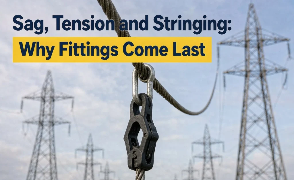
Sag, Tension and Stringing: Why Fittings Come Last
Watch a crew string a new line and the sequence looks almost backwards. The conductor goes up first, gets pulled, gets measured, gets adjusted, and only then does anyone reach for a suspension clamp or a tension clamp. Crews new to overhead work sometimes ask why the hardware cannot go on during the pull — it would save a pass along the line. The answer is that fittings do not define the line. The line defines the fittings, and until sag is final there is nothing for a fitting to be positioned against.
Sag and tension are one quantity seen from two directions: fix one and the other follows. Everything a fitting does — hold the conductor at a height, transfer tension into a tower, keep sub-conductors apart — is measured relative to that geometry. Install hardware before the geometry is correct and a number nobody has checked gets locked in. What follows covers what sag and tension describe, how stringing sets them, how sag is observed, and where the hardware belongs. No sag tables, tension values or temperature corrections appear here: those come from the line design and the conductor data for the actual span, and do not transfer between projects.
What Sag and Tension Actually Describe
A conductor hung between two points takes the shape of a catenary, close enough to a parabola over normal span-to-sag ratios. Sag is the vertical distance from the chord between supports to the lowest point. Tension is the horizontal component of the pull the conductor carries. For a level span the two are tied together simply: sag rises with weight per unit length and with the square of the span, and falls as tension rises. Double the span and sag roughly quadruples at the same tension; double the tension and sag halves.
Two consequences matter for hardware. First, sag is not cosmetic — it is a clearance budget. Ground, building, road and vegetation clearances are all set by the sag at the worst condition the design anticipates. Strung too tight, a span loses clearance in heat or ice; strung too loose, it may violate clearance at the tower and swing further in wind.
Second, the relationship is non-linear in span, so a span error is amplified. A small percentage error in measured span turns into roughly double that percentage error in calculated sag at constant tension, before any temperature correction. A crew using the design span instead of the as-built span is working from a number that was never true on this line.
Between those anchors sits the hardware. Every clamp is a point where tension is interrupted, redistributed or terminated. A подвесной зажим carries the vertical component and a fraction of the unbalanced pull; a tension clamp carries full conductor tension into the tower. Neither can be positioned before the conductor is where the design says it should be.
The Tension Budget the Hardware Has to Survive
Design tension is not a single number. The line is designed so tension stays inside limits at every condition it will meet: everyday temperature, maximum operating temperature, wind, ice, and the creep that accumulates over decades. The governing case is rarely the mild day on which the crew is stringing.
What the fitting sees on installation day is therefore a partial picture, and hardware cannot be selected from stringing tension alone. A tension clamp is chosen against the conductor’s calculated strength and the maximum tension the design allows, with a margin set by the project specification. A suspension clamp is chosen against the vertical load it carries plus the slip behaviour required — which is why grip strength is tested as a separate property rather than assumed from body strength. The slip test method is worth reading alongside any stringing plan: a clamp that slips under unbalanced pull changes the sag of the adjacent spans.
There is also a load path that shows up on site as deformation. An undersized or seized sheave flattens or scores the outer layer during pulling, and that damage then sits under the clamp for the life of the line — which is why conductor repair decisions belong in the stringing procedure, not in a separate maintenance document.
Why Fittings Come Last
Four reasons, in order of how much trouble each causes when ignored.
Tension cannot be adjusted through an installed clamp. Pulling to design sag needs the conductor running freely through suspension points and terminated temporarily at the dead-ends. Once a tension clamp is made off, the conductor length to the next span is fixed. Any later correction means re-making the termination or cutting and re-terminating — the operation a tension clamp is least suited to repeating. The tension clamp installation sequence assumes a conductor already pulled, marked and checked.
Sag is measured on a free conductor. Every observation method below depends on the conductor hanging in its own catenary with nothing else acting on it. A clamp body adds mass at a point, armour rods add stiffness, a damper adds a concentrated force. Measure with hardware on and you are reading a slightly different curve than the one in the stringing sheet.
Clamp position is derived, not chosen. A suspension clamp sits at the tower, but the conductor mark that tells the crew where the tower falls is set during pulling. Install hardware before that mark is verified and the clamp lands wherever the conductor happened to be — the span lengths either side are no longer design values, and on a long line the error accumulates tower by tower.
Installation damage is invisible once covered. A clamp mouth hides the conductor surface. A kink from a bad sheave, a burr from a tool, a nick from a dropped fitting is sealed under the clamp and becomes a fatigue origin. Field experience with aeolian vibration damage is consistent: failures start at the clamp mouth, in the region nobody can see after assembly.
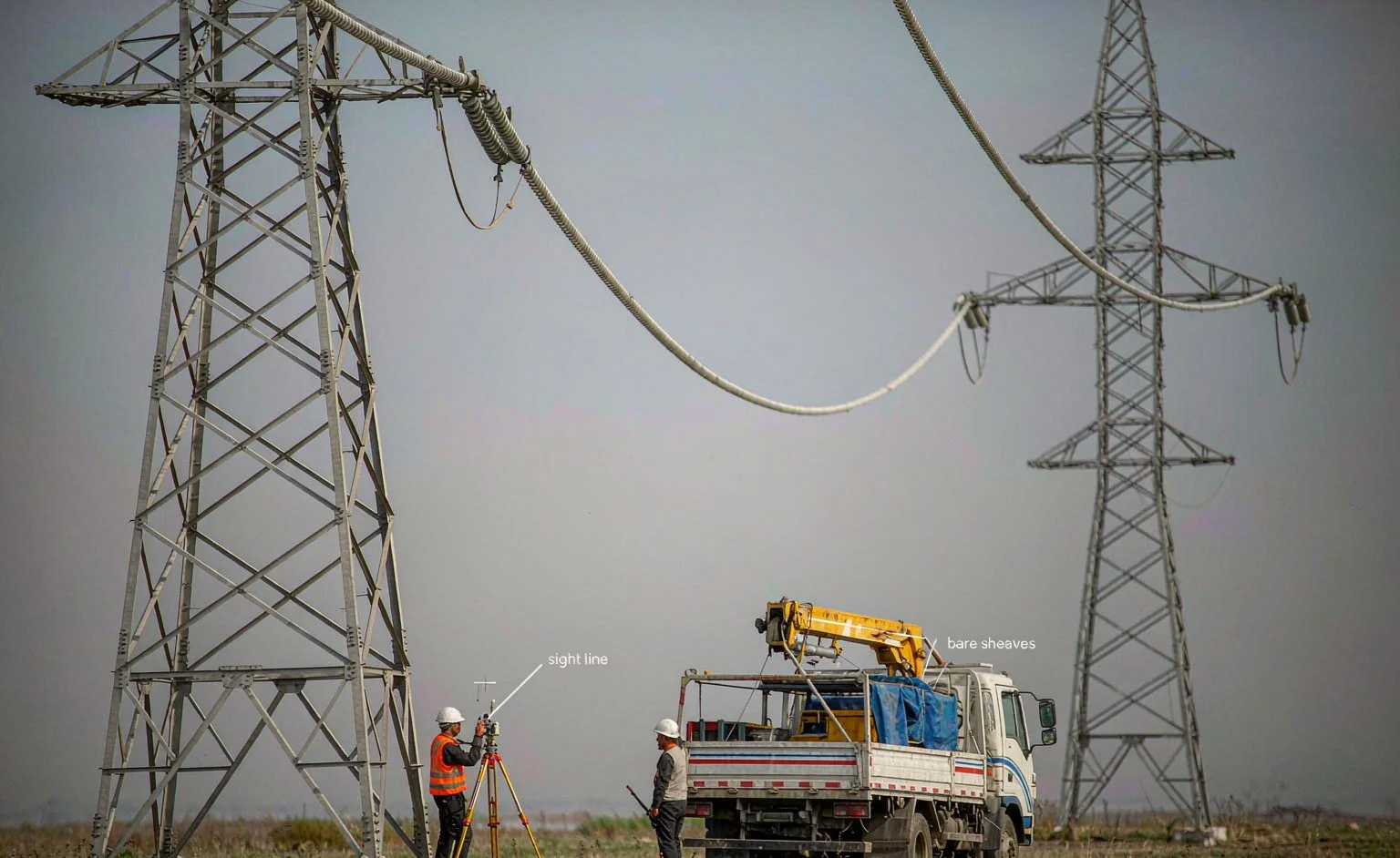
The Stringing Sequence, Stage by Stage
The order below is normal for overhead distribution and transmission work. Details vary by utility and contractor; the dependency chain does not — each stage produces the input the next one needs.
| Stage | What happens | What it produces | Hardware state |
|---|---|---|---|
| 1. Preparation | Towers checked for plumb and fastener condition, sheaves hung and inspected, pulling and braking equipment set, guard structures in place | A free running path with known sheave condition | No conductor hardware; tower attachment points only |
| 2. Pulling | Pilot line, then conductor pulled through the sheaves at controlled tension and speed | Conductor in position, still free to move at every suspension point | None; sheaves carry the conductor |
| 3. Rough tensioning | Pulled to a tension near target, allowed to settle, then measured | First sag reading and the temperature at which it was taken | None; terminations temporary |
| 4. Sag observation | Checked span by span against the stringing sheet, corrected where out of tolerance | Final conductor geometry | None; conductor still free |
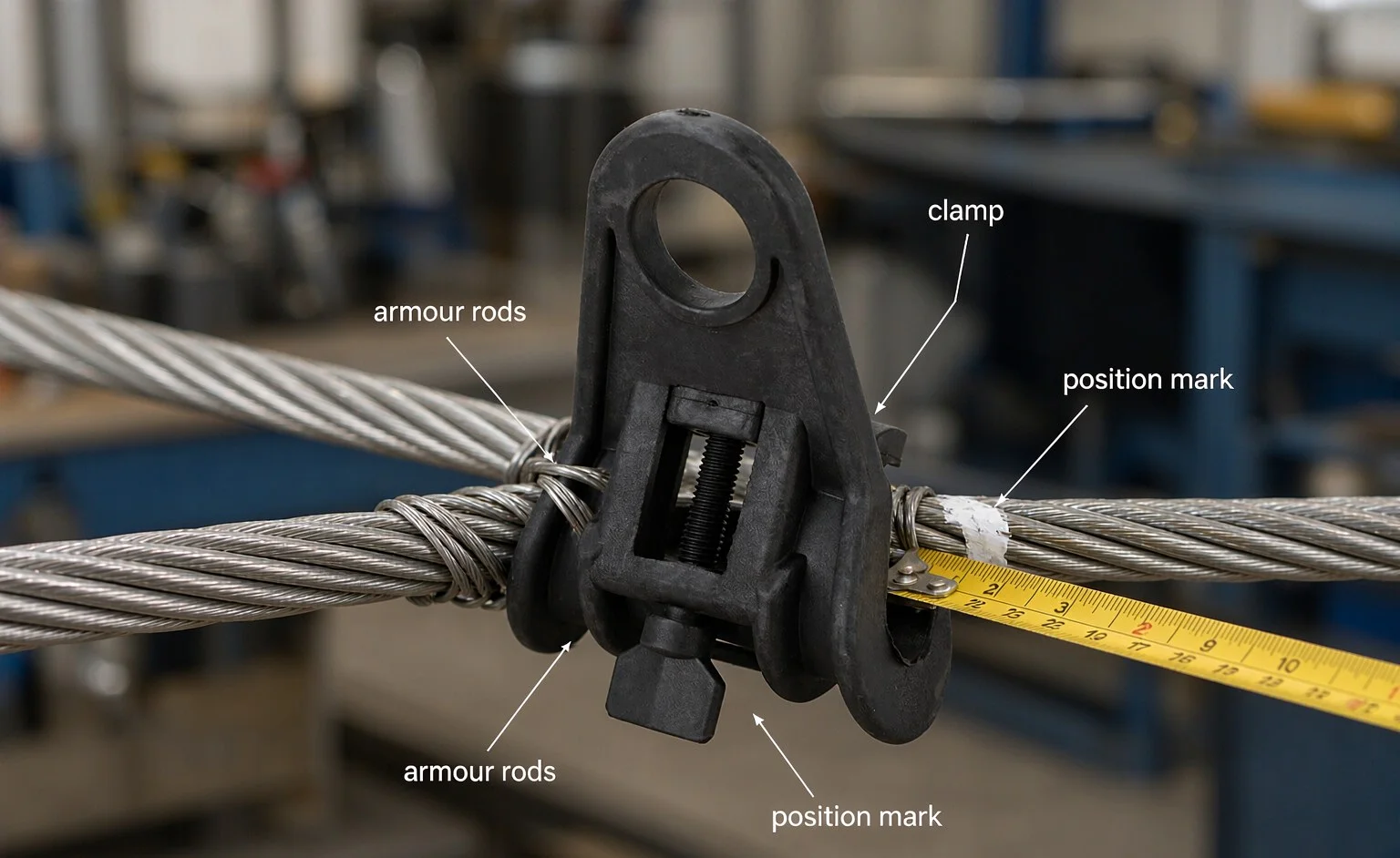
| 5. Marking | Clamp positions marked from tower centre line, allowing for clamp length and armour rods | Positions that make span lengths match design | None |
| 6. Hardware installation | Armour rods, suspension clamps, spacers or dampers, then dead-end terminations | A mechanically complete line | All fittings go on here, in fixed order |
| 7. Release and record | Temporary ties and pulling equipment removed, as-built sag and temperature recorded | Documentation for the inspection file | Complete |
Stage 5 is where most disputes originate. Marking a clamp position is not simply “at the tower”: the clamp has a physical length, armour rods extend the contact region, and the conductor must sit so the vertical load passes through the intended point. Marking from the wrong reference — tower leg instead of centre line, sheave position instead of attachment point — shifts the clamp and silently redistributes load between adjacent spans.
For bundled conductors the order shifts slightly, because spacers and spacer dampers are position-critical and go on after all sub-conductors reach final sag. Installing a spacer while one sub-conductor is still being adjusted forces the bundle into a shape it was not designed for and pre-loads the spacer frame.
How Sag Is Actually Observed
Three methods do most of the work, and a competent crew knows which one the stringing sheet assumes.
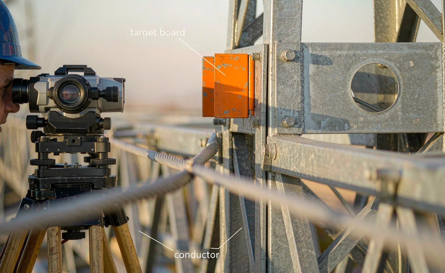
Sighting to a target
The classic method. A target is set on one tower at the calculated sag below the attachment, and the observer sights from the other tower; the conductor is adjusted until its low point lines up. Accuracy depends on the target being set for the conductor temperature at the time of observation, on the observer’s eye being at the right height, and on the span being reasonably level. On long spans with significant elevation difference the plain target value is wrong and a correction from the stringing sheet must be applied.
Total station or transit
The instrument measures vertical angles to the conductor at one or more points and sag is computed from the geometry. This handles elevation difference and long spans better than a sight board, and it produces a record. It is slower per span; the usual failure is measuring to a point that is not the low point of the span.
Tension measurement
A dynamometer in the pulling line reads tension and sag is inferred. Useful during rough tensioning, but it measures tension at the pull rather than in the finished span, and does not account for friction in the sheaves along the way. Treat it as a control during pulling, not as the acceptance measurement.
Temperature, Creep, and the “Today’s Sag” Trap
Sag tables are written against conductor temperature, because a conductor expands as it warms. The crew observes sag at whatever temperature the conductor happens to be and compares against the value the sheet gives for that temperature. Two errors follow.
The first is using air temperature. Conductor temperature under load or in sun is higher than ambient — sometimes substantially — and the difference depends on current, wind and solar exposure. A sheet that specifies observation at conductor temperature requires that temperature to be established, not assumed from a thermometer in the shade. Some crews leave a short sample of the same conductor in the same exposure and measure it; others work from the ambient, wind and load relationship in the design data.
The second is forgetting creep. A new conductor keeps elongating under sustained tension for months, so the sag observed on day one is not the sag after a year of service. Design accounts for this with an initial condition and a final condition after creep, and the stringing sheet states which one the crew is setting. Setting final sag on new conductor means over-tensioning deliberately — a decision for the design engineer, not the crew. Setting initial sag and leaving it is normal and correct, but the line will sag further, and a clearance check the following week should not be read as a failure.
Both points have a hardware consequence. Armour rods, clamps and dampers are positioned relative to the conductor as it sits at installation. If the conductor later creeps and the clamp body rotates slightly in its attachment, damping characteristics change a little. Nothing dramatic, but it is one reason periodic fitting inspection should include clamp rotation and dampers that have drifted out of position, not only missing parts.
Where the Fitting Goes: Placement and Tolerance
Once marking is done, assembly at a suspension point generally runs: armour rods if specified, clamp body, keeper and fasteners, then any damping or spacing accessory. The Руководство по установке подвесного зажима covers the mechanics; the tolerance question is what matters here.
Placement tolerance is not about tidiness. Each span’s sag is set by the conductor length between its two end attachments. A clamp placed well off the mark at tower N gives conductor to one span and takes it from the other. On a short distribution span that is a measurable fraction of design sag; on a long transmission span it is negligible. The project specification reflects that, usually as a longitudinal distance, sometimes tighter at dead-ends than at suspension points.
Two related items get less attention than they deserve. The first is vertical position within the attachment: a clamp hanging from a shoe or bracket in the wrong orientation puts the conductor at a different height than the design assumes, changing tower clearance without changing span sag — a common finding where the hardware set came from a generic bill of materials rather than the tower drawing. The second is the interaction between clamp type and conductor. Compression, bolted, wedge and preformed tension clamps all terminate tension but stress the conductor differently at the transition from clamped to free: preformed and armour-rod-protected terminations spread bending strain over a longer length, a bolted clamp concentrates it at the last bolt. Where vibration exposure is high, that difference is the design margin.
Mistakes That Come Back as Claims
These are the errors most often followed by a complaint about fittings — usually filed against the hardware when the cause was upstream in the stringing sequence.
| What was done | What it looks like afterwards | What should have happened |
|---|---|---|
| Sag set by feel, without an observation | Clearance marginal on some spans, generous on others; adjacent spans visibly uneven | Sag observed span by span against the sheet at measured conductor temperature |
| Clamp installed before final sag was confirmed | Span lengths off design; clamps off tower centre line; re-work or accepted deviation | Mark only after sag is signed off, then install hardware |
| Conductor pulled over a seized or undersized sheave | Flattened or scored outer strands under the clamp; fatigue breaks at the clamp mouth later | Sheave inspection before pulling, correct groove size, pull speed and tension limits followed |
| Armour rods omitted where specified, clamp on bare conductor | Crushed or nicked aluminium strands, higher bending strain at the clamp exit | Rods fitted per the hardware drawing, ends dressed so they cannot lift under vibration |
| Clamp fasteners run down with an impact tool and not checked | Under- or over-torqued bolts; loose keepers found at first inspection | Fasteners set to the value in the manufacturer’s data with a calibrated tool, then marked |
| Spacers installed before all sub-conductors reached final sag | Splayed bundle, spacer frames loaded, sub-conductor spacing uneven | Bundle sagged and checked first, then spacers at specified positions |
| Damaged conductor left in place because it sat under a clamp | A repair job two winters later, with the clamp as the only suspect | Damage assessed and repaired per the stringing procedure before the clamp closes over it |
The pattern is consistent: hardware gets blamed for a geometry error created before the hardware was touched. When a customer reports early clamp failures, the useful first question is not which clamp was used but what the sag record for those spans says.
Specifying Fittings Before the Stringing Plan Exists
Fittings are usually ordered months before the stringing sheet is issued, which leaves the buyer specifying hardware without as-built spans. The overhead line fittings RFQ checklist covers the full list; for a stringing-driven purchase the critical items are:
- Conductor identity, not just area. Stranding, temper and nominal diameter set both the clamp groove and the grip behaviour. Two conductors of the same nominal area but different stranding are not interchangeable in a clamp.
- Design tension range and governing condition. This tells the supplier whether the termination holds near the conductor’s limit or comfortably below it, and whether armour rods are needed.
- Whether the line is bundled, and the bundle geometry. Spacer and damper selection depends on sub-conductor spacing and vibration environment, not on the conductor alone.
- Corrosion environment and coating requirement. The clamp body material question is answered by exposure, stated rather than assumed from a generic description.
Covered overhead distribution differs enough to separate: on aerial bundled cable systems the messenger or insulated neutral carries the mechanical load, sag is set on that member, and the insulated phases are positioned relative to it. Hardware is therefore specified against the messenger, and the phase conductors are held by accessories carrying no tension at all.
Field Checks After the Stringing Is Released
With temporary equipment off and the line at final position, a short set of checks closes the loop and creates the record any later claim will be judged against.
- As-built sag recorded per span, with conductor temperature and method used.
- Clamp positions checked against marks, deviations noted rather than corrected silently.
- Fastener torque verified on a sample of suspension clamps and all dead-ends, with the tool’s calibration status recorded.
- Armour rod ends, damper and spacer positions confirmed against the hardware drawings.
- Conductor surface inspected at every clamp exit, both sides, before energising — the last moment that region is visible without opening a clamp.
Часто задаваемые вопросы
Can fittings be installed during pulling to save a pass?
Not without giving up control of sag. A tension clamp fixes conductor length from that point onward, and a suspension clamp fixes the conductor at a point before its position has been verified. The saving is one pass along the line; the cost is that geometry in every span after the first clamp is no longer adjustable. On short low-voltage work some crews combine stages, but where sag is a clearance issue the separation exists for a reason.
Will the sag I measure on installation day match next year?
No, if the conductor is new. It creeps under sustained tension, so sag increases over the first months of service. The stringing sheet states whether an initial or final condition is being set, and that governs what “correct” means on the day. Do not treat post-creep sag as an installation defect without checking which condition was specified.
How do I know whether a clamp position error matters?
Compare the deviation against the tolerance in the project specification, which is written for span length and voltage class. A deviation negligible on a long transmission span can be a real sag error on a short distribution span. The judgement is arithmetic against the design, not visual, and the stringing sheet is the reference.
Why do failures appear at the clamp mouth rather than mid-span?
Because bending stiffness changes abruptly where the conductor leaves a rigid body. Alternating bending strain concentrates in the first short length beyond the clamp — also the region hidden from inspection. Protection works by spreading that strain over more conductor length, and where exposure justifies it the decision is made at design stage, not at installation.
Closing
The sequence exists because a fitting is a measurement of where the conductor is, not a device that puts it somewhere. Sag and tension decide the geometry; hardware secures that geometry and transfers its loads into the structures. Getting the order right costs one extra pass along the line. Getting it wrong costs a re-termination, an uneven line, or a fatigue failure that surfaces years later under a clamp nobody thought to open.
For buyers, the practical takeaway is that stringing information belongs in the enquiry even while the stringing plan is still being written: conductor stranding, design tension range, bundle geometry, tower attachment and exposure. Those five decide the hardware; everything else is detail on top of them.