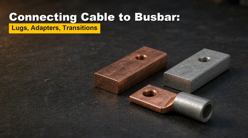
Connecting Cable to Busbar: Lugs, Adapters, Transitions
A cable run rarely ends at a cable. It ends at a bar — a copper busbar in a panel, an aluminium bar on a pole-mounted bracket, a galvanised steel frame on a structure — and the joint where the two meet is the part of the installation most likely to heat up, corrode, or come loose. The cable itself is usually well chosen. The bar is usually well sized. The connection between them is where the decisions get made quickly and checked rarely.
The reason is that this joint has to solve two problems at once. It has to carry current across a mechanical interface, which means contact area and contact pressure, and it has to survive the chemistry between two different metals in whatever air the installation sits in. A lug that is perfect for a copper-to-copper joint is the wrong part on an aluminium bar, and a joint that measures fine on the day of commissioning can be the hottest point in the panel two years later.
Three Interfaces, Not One
It helps to stop thinking of “connecting a cable to a busbar” as a single operation. There are three distinct interfaces in the assembly, and they fail for different reasons.
The first is the cable-to-lug interface, inside the barrel. This is a compressed joint: the conductor and the barrel become one piece of metal, and the only variables are the die, the strip length and the conductor condition. Once made correctly it is stable for the life of the installation, because there is no removable interface to loosen.
The second is the lug-to-bar interface, at the palm. This is a pressure contact: two flat faces held together by a bolt, with current crossing the boundary between them. It is the interface that decides whether the joint runs cool, and it is the one that depends on surface preparation, flatness, bolt tension and washer choice.
The third is the bar-to-bar or bar-to-frame interface, behind the connection point. On a copper bar bolted to a galvanised steel frame, this is a dissimilar-metal joint that nobody thinks about because it is not where the cable is. It corrodes anyway.
Most connection problems that get blamed on the lug are actually problems at the second or third interface. That is worth establishing before changing the part number.
Why Copper on Aluminium Is the Hard Case
Copper to copper is a solved problem. Two clean copper faces under bolt pressure form a joint with low and stable resistance, and the only real enemy is surface contamination introduced during assembly.
Aluminium changes the problem in two ways, and both are chemistry rather than mechanics.
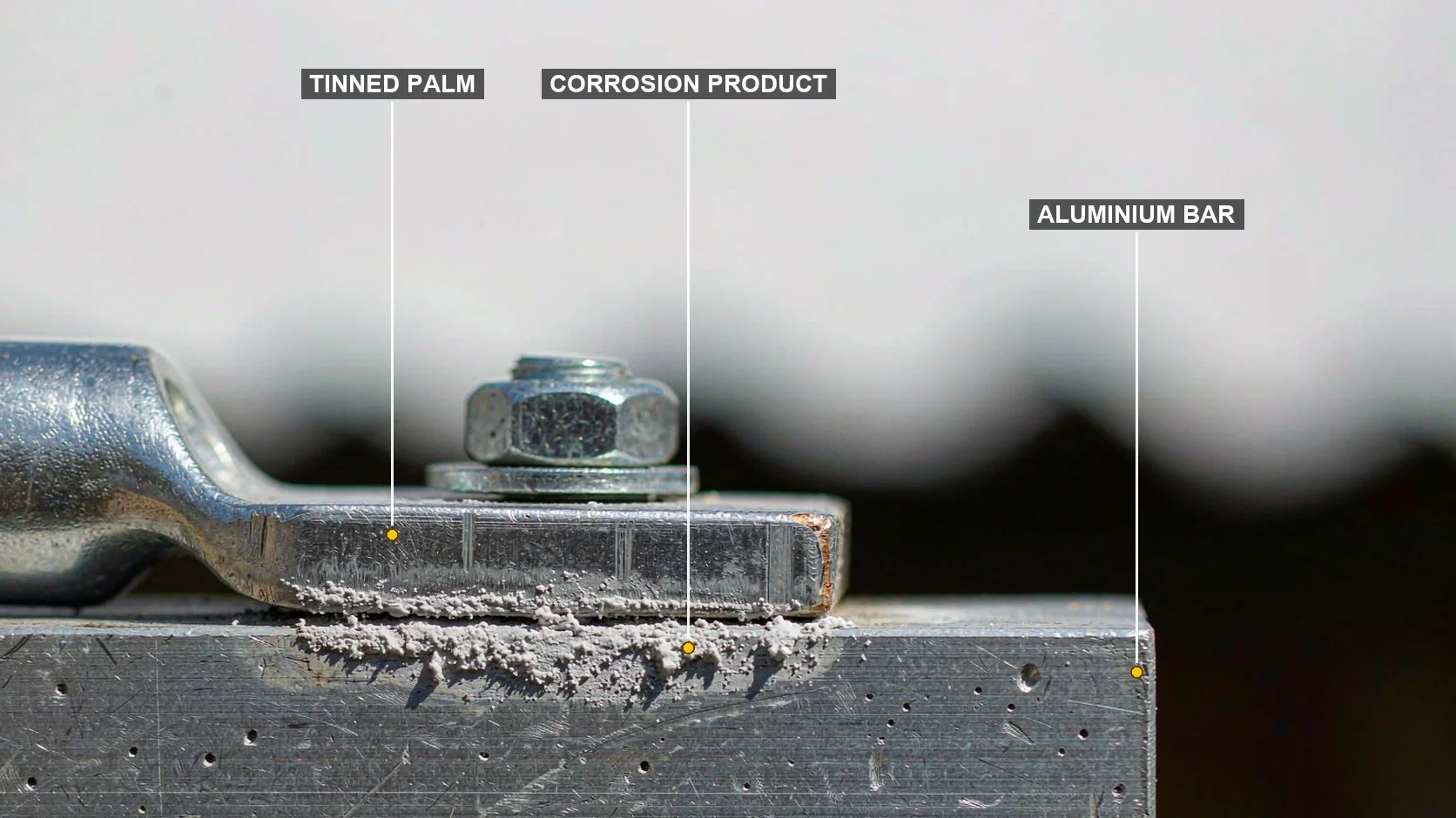
The first is the oxide layer. Aluminium oxidises almost immediately on exposure to air, and the resulting film is hard, electrically resistive and self-healing — remove it and it comes back within minutes. A bolted joint relies on metal-to-metal contact at the microscopic asperities where the two faces actually touch. An insulating film across those asperities defeats the whole arrangement, which is why an aluminium joint that looks properly tightened can still measure badly. The film has to be broken mechanically at the moment of assembly, and it has to be kept from re-forming in the interface afterwards. That is what abrasive preparation followed by a contact compound is for, and it is not optional on aluminium.
The second is galvanic corrosion. Copper and aluminium sit far apart in the galvanic series, and when the pair is wetted — by condensation, by rain, by washdown — the aluminium becomes the anode and corrodes preferentially at the joint. The corrosion product is bulky, so it pushes the faces apart, which raises resistance, which raises temperature, which accelerates the corrosion. The joint degrades in a spiral rather than linearly, and it does so fastest in exactly the places where aluminium is used outdoors.
The mechanism is the same one described for the lugs themselves in Copper vs Aluminium Cable Lugs. What changes here is the scale: on a busbar connection the dissimilar interface is larger, more exposed, and often carrying more current, so the consequences arrive sooner.
Three Ways to Make a Transition
When the conductor and the bar are different metals, the joint needs a transition, and there are three established ways to build one. They are not interchangeable, and the choice is driven by current, environment and how the part is made rather than by preference.
Friction welding. A copper palm and an aluminium barrel are rubbed together under pressure until the interface reaches a temperature where the two metals bond without melting either in bulk. The result is a joint with a genuine metallurgical bond and a narrow transition zone. Friction-welded bimetal lugs are the usual choice for terminating aluminium cable on copper equipment where the connection must be permanent and the part is made in volume.
Flash welding. The two parts are pressed together while an arc flashes across the interface, melting a thin layer on each and forging them together as the pressure closes. It produces a similar finished part by a different route, with a wider heat-affected zone. Both processes give a joint that will not separate in service; the difference is in the metallurgy around the boundary and in what the supplier’s process control looks like, which is a question for the data sheet rather than for the drawing.
Mechanical crimp with a transition shim. A standard aluminium barrel is crimped onto the aluminium conductor, and the palm side is a separate copper or tinned plate, or the joint is made with a bimetallic shim between the palm and the bar. This is the approach used where a bimetal lug is not available in the size required, or where the connection is made on site with hand tools. It depends entirely on assembly discipline: the shim has to be clean, correctly placed, and compressed evenly, and a shim that is cocked or contaminated is worse than no shim at all.
| Transition method | How the bond is made | Where it suits | What to watch |
|---|---|---|---|
| Friction welding | Solid-state bond under pressure and rotation | Volume-produced bimetal lugs for aluminium cable on copper equipment | Transition zone position; whether the palm and barrel are dimensionally to the drawing |
| Flash welding | Arc-flash melting plus forging | Same duty as friction welding, different production route | Width of the heat-affected zone; process control evidence on the data sheet |
| Mechanical crimp with transition shim | Compression plus a bimetal or plated shim at the palm | Site-made joints, non-standard sizes, repair work | Shim cleanliness and placement; even compression; re-checking after assembly |
| Bolted adapter or transition bar | Two bolted interfaces with a bimetal or plated plate between them | Where the cable cannot be cut, or the bar is inaccessible | Two pressure contacts instead of one; each must be prepared separately |
The internal structure of a bimetal lug is covered in Bimetallic Cable Lugs and is not repeated here. This page stays with the node as a whole: what the joint has to achieve, and what has to be done to each face in it.
When a Lug Is the Wrong Answer
A crimped lug assumes three things: that the cable can be cut, that there is room to get a die onto the barrel, and that the connection can be made once and left alone. In a panel those assumptions usually hold. In the field they often do not.
Where a cable is continuous and cannot be cut — a live run being tapped, a repair on a cable that is still in service elsewhere — a bolted clamp or an adapter is the right family. A bolted terminal clamp grips the conductor with a mechanical jaw and presents a palm or a pad to the bar, so the connection is made without cutting and can be reopened. The trade-off is that a clamped conductor joint depends on sustained jaw pressure, and on aluminium that means creep and re-tightening. Conductor-to-conductor joints on aluminium are a different problem, covered in Aluminium Cable Joints; here the second member is always a bar, not another cable.
Where the bar is inaccessible, or where the connection has to be made at an angle the cable cannot reach, a transition bar or an adapter plate moves the interface to somewhere workable. This adds a second pressure contact to the circuit, and every additional contact is another place to prepare, tighten and inspect. Two clean interfaces are better than one badly made one, but a chain of adapters is a chain of risks and should be justified rather than defaulted to.
The shapes available across the lug family are in Cable Lug Types, and the naming conventions that separate a lug from a clamp from an adapter are in Lug, Thimble, Ferrule, Sleeve. Both are useful before the enquiry, not after.
Preparing the Bolted Face
The palm-to-bar interface is where a cable-to-busbar joint is won or lost, and the preparation is unglamorous. Four steps, in order.
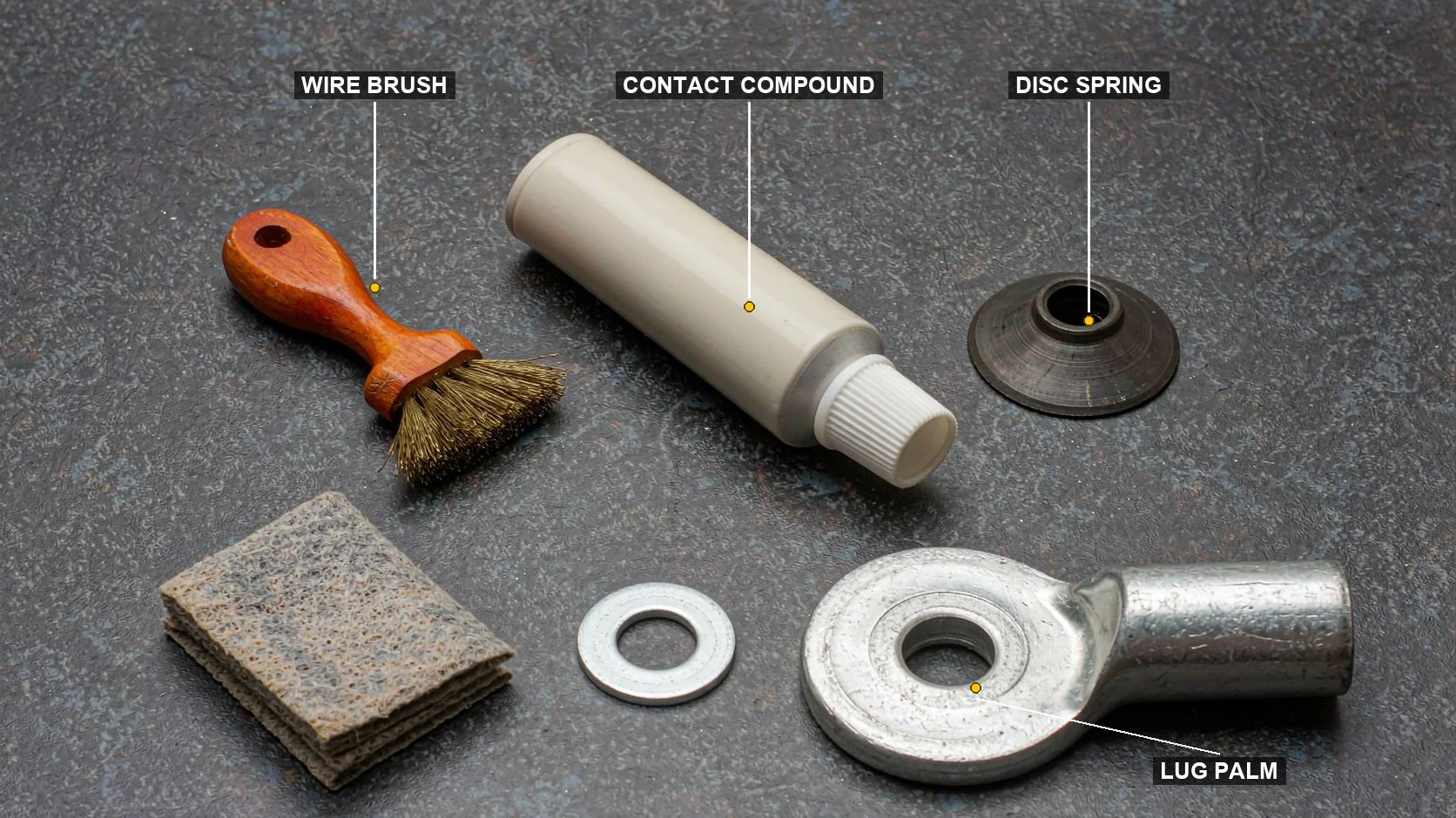
Remove the oxide, mechanically, immediately before assembly. On aluminium this is not a cleaning step but a manufacturing step: the film re-forms quickly, so the abrasion and the assembly have to be close together in time. A wire brush or an abrasive pad used in one direction leaves a surface that will take contact; a solvent wipe alone does not, because it removes dirt and leaves the oxide.
Apply a contact compound where the design calls for it. The compound’s job is to exclude air and water from the interface so the oxide cannot re-form and the galvanic cell has no electrolyte. It is not a substitute for removing the oxide first, and it is not a conductor in its own right — a joint relying on paste to carry current is a joint that has already failed. Whether paste is specified is a project decision, and on aluminium it usually is.
Use a bimetallic interface where the metals differ. A copper or tinned transition plate between an aluminium bar and a copper lug converts one dissimilar joint into two similar ones, or at least into joints with a much smaller potential difference. The plate has to cover the full contact area, not just the bolt hole.
Hold the tension with the right washer stack. A disc spring or a conical washer maintains clamp load as the joint relaxes through thermal cycling and, on aluminium, through creep. A plain flat washer spreads the load but stores nothing, so the first relaxation is permanent. The order matters: the spring element bears on the bolt head or nut, the flat washer protects the palm, and the assembly goes together dry and clean unless the specification says otherwise.
Hole, Bolt and Clamp Pressure
The hole in the palm and the bolt through it look like the simplest part of the job and are the most common source of a joint that never runs cool.
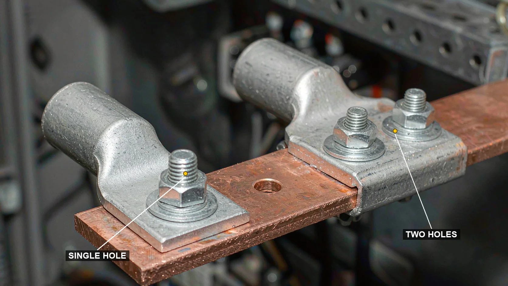
Hole size sets contact area. A palm with a hole much larger than its bolt has less metal around the bolt, and the clamp pressure is concentrated in a smaller annulus. The instinct that a bigger hole fits more equipment is exactly backwards: an oversized hole on a small bolt reduces the contact area and can let the palm shift under load. The hole should match the stud, and where a range of studs must be accommodated, the palm width should be chosen for the largest one in the range.
Palm width and edge distance decide whether the washer sits flat. A washer that overhangs the edge of a narrow palm bears on air on one side, tilts, and applies uneven pressure. Two-hole palms with a defined pitch exist for exactly this reason: two bolts resist rotation and keep the pressure distribution symmetrical, which matters on bars carrying heavy current and on anything subject to vibration.
Bolt grade and bar thickness belong together. A high-grade bolt tightened against a thin bar deforms the bar rather than clamping the joint, and the pressure is lost as soon as the bar yields. Where the bar is thin, a thicker pad or a backing plate is part of the connection design, not an accessory.
Bar hole and palm hole must agree on pitch. A two-hole palm drilled to one pitch will not fit a bar drilled to another, and drilling out the palm to suit is the wrong repair: it removes the very material carrying the clamp load. The right answers are a correctly pitched bar, a transition plate, or a different lug — not a bigger drill.
Indoor and Outdoor Are Different Problems
Inside a panel, the joint is protected from rain and from most of the airborne chloride and sulphur that drive corrosion. The dominant risks are assembly error, vibration and thermal cycling. The preparation steps above still apply, but the environment does not push back.
Outdoors, everything changes. Water sits in the interface, condensation cycles daily, and on a coastal site the air carries chloride that attacks both the aluminium and any exposed steel hardware. Under those conditions three things matter more than they do indoors: the transition between dissimilar metals, the sealing of the interface against water, and the corrosion protection on the fasteners. A joint that is merely adequate indoors will fail outdoors, and it will fail at the aluminium side first.
Where the bar itself is galvanised steel rather than copper or aluminium, the pair is steel-to-copper, and the zinc coating becomes the sacrificial element. That is a reasonable arrangement as long as the zinc is allowed to do its job and the copper face is protected at the interface. It is a bad arrangement when the steel is painted over at the joint, because the paint both hides the corrosion and insulates the contact. The wider question of how a site’s environment should be graded is in Fittings for Coastal and Industrial Areas.
Comment choisir le bon modèle
The table converts a described connection into a part family and the parameters that have to be stated with it. The first column is what the installation actually looks like.
| Connection to be made | Part family to specify | Parameters that must be stated |
|---|---|---|
| Copper cable to copper bar, permanent | Standard copper or tinned copper lug, crimped | Conductor range; stud hole diameter; palm width; one hole or two, with pitch; bar thickness; indoor or outdoor |
| Aluminium cable to copper bar | Bimetallic lug, friction or flash welded | Aluminium conductor range; palm hole and width matching the bar; transition method; whether the joint is exposed |
| Copper cable to aluminium bar | Copper lug plus a bimetallic transition plate, or a tinned lug with prepared interface | Conductor range; bar hole pitch; plate dimensions; contact compound specified or not; fastener material |
| Aluminium cable to aluminium bar | Aluminium lug, crimped, with prepared and compounded interface | Conductor range; hole and pitch; bar thickness; whether the joint is indoor or exposed; re-tightening interval |
| Cable to galvanised steel frame or structure | Copper lug plus a bimetallic plate, or a tinned lug with an insulating separator where the frame is not a conductor | Conductor range; bolt size and grade; frame thickness; whether the frame is part of the earthing path |
| Continuous cable, connection without cutting | Bolted terminal clamp or adapter | Conductor range; pad or palm dimensions; bolt size; whether the clamp must accept two conductors |
| Bar not reachable at the cable angle | Transition bar or adapter plate | Both interface dimensions; current path length; number of bolted interfaces added; environment |
Where any of these cannot be answered from the drawing, it has to be asked rather than assumed. A palm width guessed at the quotation stage is a joint that will not fit at installation, and a bar thickness guessed at is a joint that will not hold its clamp load.
The models currently listed are on the cable terminals category page for the termination range, and on the busbar accessories category page for the bar-side hardware. The busbar accessories category lists a limited number of models; anything not listed there has to be confirmed against a drawing before it is quoted, and this page does not claim the full range is available.
FAQ
Can a copper lug be bolted directly to an aluminium busbar?
It can be done and it will work for a while. In dry indoor conditions with a properly prepared, compounded interface, a direct joint is common practice. Outdoors or in a wet environment the galvanic couple will attack the aluminium, and a bimetallic transition plate is the better answer. The decision is about the environment as much as about the metals.
Is contact paste necessary on a copper-to-copper joint?
Not always, but it is cheap insurance on anything exposed. On a clean indoor copper-to-copper joint assembled promptly, the paste adds little. On a joint that will sit for years, or one assembled in humid conditions, it keeps the interface from oxidising before the bolt is tightened and afterwards.
Why does an aluminium busbar joint loosen over time?
Aluminium creeps under sustained load, so the clamp force relaxes even when nothing has moved. Thermal cycling accelerates it. A disc spring washer maintains load across that relaxation, and a re-tightening interval is part of the maintenance plan rather than a sign that something was done wrong.
Does the bolt grade matter if the bolt is not carrying current?
It matters because the bolt carries clamp load, and clamp load is what makes the contact. A bolt that yields or relaxes loses the joint. The grade, the washer stack and the bar thickness have to be considered together.
What is the difference between a transition lug and a transition plate?
A transition lug does the metal change inside the part, between barrel and palm. A transition plate does it at the bolted interface, as a separate piece between the palm and the bar. The lug is a cleaner solution where it exists in the right size; the plate is what you use when it does not.
The joint between a cable and a bar is a small piece of engineering with a disproportionate share of the failures, because it is the only part of the run where two metals, two surfaces and a bolt all have to agree. Getting it right is mostly a matter of naming the metals on both sides, preparing the faces properly, and choosing a fastener stack that keeps its pressure. None of that is difficult; all of it is easy to skip.
If you are specifying a cable-to-busbar connection and want the part matched to the conductor, the bar and the environment, send the conductor material and range, the bar material and thickness, the hole diameter and pitch, whether the joint is indoor or exposed, and whether the cable can be cut. The termination range is on the cable terminals category page, and the bar-side hardware on the busbar accessories category page. Where a dimension is not documented it will be queried rather than assumed, and where a model does not exist for the combination, that will be said rather than worked around.