Torque Tools on Line Crews: Calibration, Setting, Records
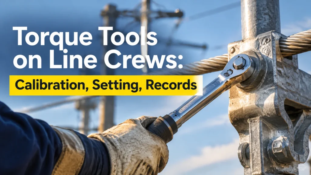
Almost every bolted fitting on an overhead line — the bolted tension clamp, the suspension clamp bolt, the insulation piercing connector, the spacer clamp — carries a torque requirement somewhere in its documentation. That number is not decoration. Below it, the clamp does not develop its rated grip; above it, the bolt stretches, the casting cracks, or the conductor is crushed at the contact point. The fitting itself may be exactly right for the job and still fail in service because of how the wrench was used on installation day.
The tool that decides this is the torque wrench, and a torque wrench is a measuring instrument before it is a tightening tool. It is only as accurate as its last calibration, only as trustworthy as the way it was set, and only as defensible as the record that says it was used. This article covers the three things that separate a line crew that gets consistent joints from one that gets lucky: keeping the tool calibrated, setting it correctly for each job, and writing down what was done.
Why Bolted Line Fittings Depend on Torque
A bolted joint works by clamping force. The bolt is a spring: turning the nut stretches the bolt, and that stretch presses the two halves of the fitting together with enough force to grip the conductor. The torque figure given in a fitting’s specification sheet is simply the turning effort that has been found — by the manufacturer’s testing — to produce the intended clamping force for that bolt, that thread condition, and that coating.
This relationship breaks quickly when the turning effort is wrong in either direction. Under-tightening leaves the joint loose, and a loose clamp on a vibrating conductor works the contact surfaces until the grip is gone; the fitting slides, or the bolt backs out entirely. Over-tightening is less obvious and more dangerous, because the joint looks perfect on inspection. The bolt has yielded, the clamp body has deformed around the conductor, and the damage is invisible until the fitting lets go under load or a corrosion crack develops months later at the overstressed point.
Both failure modes are avoidable, and neither requires exotic equipment. They require a calibrated tool set to the value stated in the fitting’s own specification sheet, used in the way the tool and the fitting were designed for. If you are unsure which fittings on your project are torque-controlled and which are not, the Comparaison des différents types de pinces de serrage separates bolted, compression and preformed designs, and the limits of insulation piercing connectors explains why the bolted IPC in particular is torque-sensitive: its blades bite into the conductor precisely because the clamp force is controlled.
Torque Tool Types Used on Line Work
Line crews meet four broad families of torque tools. Each measures or controls torque in a different way, and each fails in a different way when neglected.
| Tool type | How it works | Strengths | Limitations on line work |
|---|---|---|---|
| Click-type (preset, adjustable scale) | Spring-loaded mechanism releases at the set value and clicks | Cheap, robust, no batteries, fast to use at height | Click is easily masked by noise and gloves; needs periodic recalibration; accuracy drifts if abused |
| Beam / dial indicating wrench | Pointer or dial shows the torque as it is applied | You see the value continuously; good for verification work | Hard to read at height or in poor light; slow; pointer can be bent by rough handling |
| Electronic / digital wrench | Strain gauge reads torque, with audible and visual signals and stored readings | Built-in logging, target-value alarms, angle measurement on some models | Battery dependent; display limits with gloves and glare; needs care against moisture and drops |
| Hydraulic or battery-powered torque tool (large fittings) | Powered drive applies torque to a preset shut-off value | Consistent repeatable output on large bolts where hand effort is insufficient | Heavy, expensive, needs its own maintenance and calibration regime; reaction forces must be managed |
For most distribution and sub-transmission hardware, an adjustable click-type wrench in good condition, owned by the crew and calibrated on a schedule, does the job. Digital tools earn their cost when the contract or the client asks for torque evidence per joint, because the stored readings slot straight into the site records. Powered tools belong on the large bolted joints of heavy tension hardware, where a cheater bar on a hand wrench is the alternative — and a cheater bar is never the correct alternative. The correct approach to fastening conductors in clamps, including the sequence of tightening, is covered in the Guide d'installation des pinces de suspension et le Guide d'installation des colliers de serrage.
Choosing the Right Range for the Job
Torque wrenches are not accurate across their whole scale. Near the bottom of the range the mechanism dominates; near the top the spring is near its limit. The working rule every calibration house repeats is the same: the target torque should sit in the middle portion of the tool’s range, not the extremes. A wrench that is nominally capable of the value but only at the very top of its scale will over- or under-shoot.
On a line crew this has a practical consequence: one wrench is not enough. Fitting hardware spans small stainless bolts and large galvanized structural bolts, so a sensible kit carries at least two calibrated wrenches with overlapping ranges, chosen so that the bolts each crew actually tightens fall comfortably inside the middle of one range or the other. Which bolt sizes a crew meets is decided by the fittings on the project — the fields of a cable lug specification sheet show the same logic applied to terminal hardware: the bolt size, plating and torque class are all stated by the manufacturer, and the tool follows from the documented value, never the reverse.
Two range-related mistakes appear again and again in the field. The first is setting a wrench outside its marked range because the scale happens to extend there; if the scale does not clearly cover the value, the tool does not cover it. The second is using the wrench as a general-purpose ratchet for running bolts down quickly at full torque engagement, which hammers the mechanism. Run bolts down with a normal wrench; use the torque wrench only for the final, measured turn.
Calibration: Schedule, Certificates and Traceability
Calibration is the comparison of the wrench against a reference standard, at several points across its range, by a laboratory whose own standards are traceable. A wrench that has drifted does not look any different. The spring has simply relaxed, or the mechanism has worn, and the click that the operator trusts now corresponds to a different value than the one printed on the scale.
Three rules govern the schedule, and none of them is a number you invent:
- Calendar interval: recalibrate at the interval stated by the tool manufacturer or by the project specification — whichever is shorter. Where no interval is specified, agree one with the calibration laboratory and write it into the crew’s tool procedure.
- Event-based recalibration: any significant drop, any use beyond its range, any suspected overload, and any visible damage to the handle, scale or drive end sends the wrench back for verification before its next use — regardless of where the calendar sits.
- Certificate control: every wrench carries an identification number, and the calibration certificate for that number is kept where the site records can find it. The certificate states the measured values and the uncertainty; the crew’s tag on the tool states only the date due for recalibration.
Verification and traceability also matter at the other end of the supply chain: the incoming inspection process for line hardware checks bolts, threads and markings on the fittings themselves, and the torque documentation for those bolts should be part of the same paper trail. When a fitting’s torque class is unclear at inspection — for example, an unlabeled bolt or a substituted fastener — the correct action is to query it with the supplier before installation, not to estimate a value on the pole.
Setting the Tool Before Each Job
Most torque errors happen before the wrench ever touches the bolt. A correct setting routine takes seconds and prevents all of them.
First, find the value in the right document. The torque figure comes from the fitting manufacturer’s specification sheet for that exact fitting and bolt, or from the project specification where the engineer has stated one. It does not come from memory, from a similar-looking fitting, or from “what we always use on these”. Where a fitting offers no published figure, the matter goes back to the supplier — a documented gap is a procurement question, not a field decision.
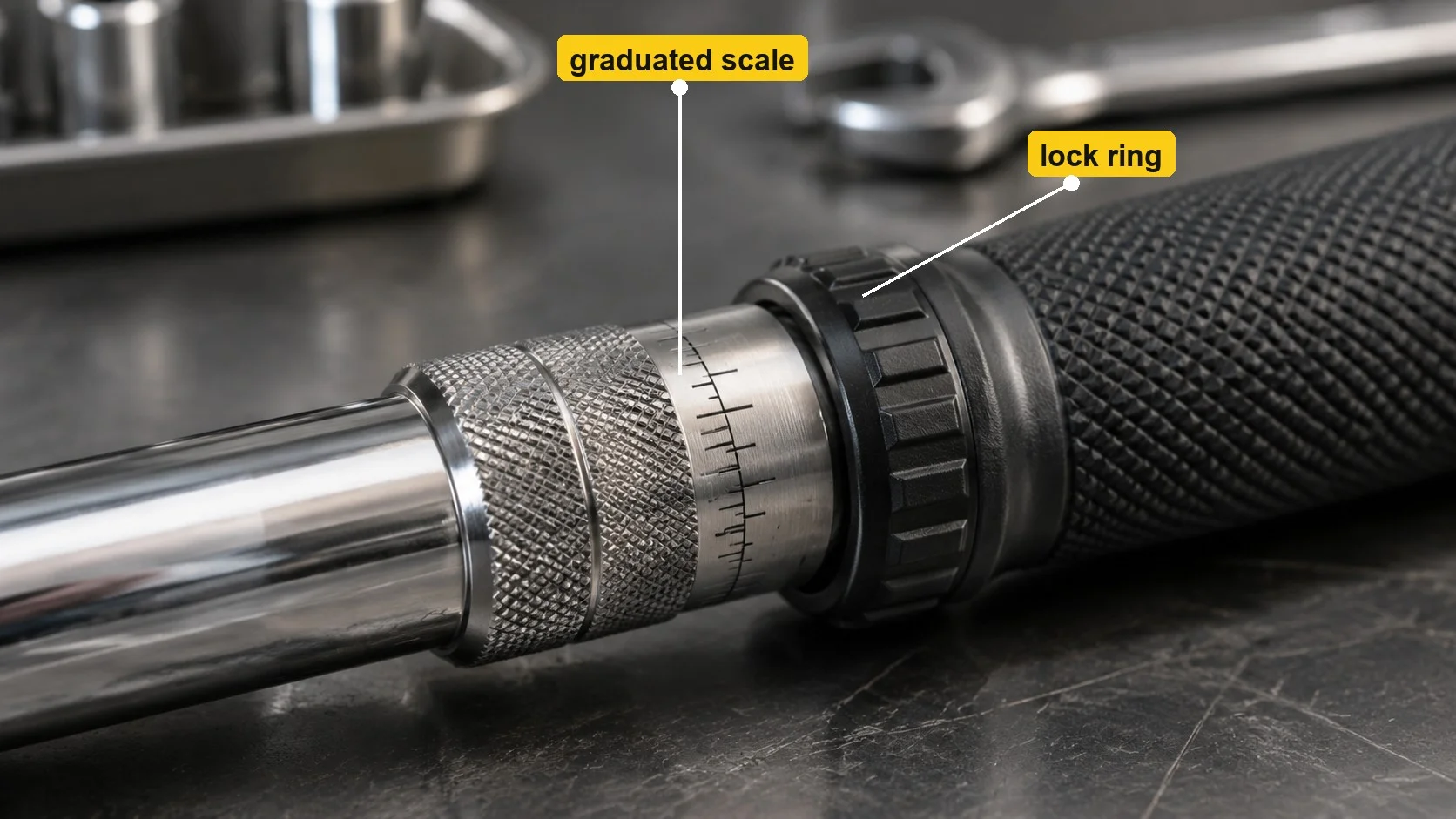
Second, unlock the scale, set the value, and lock it again. On a twin-scale wrench read the unit system the drawing actually uses; mixing units is one of the largest single-error sources in bolted hardware, because the resulting setting looks entirely plausible on the scale while being far from the intended value.
Third, verify what you set. Two practical habits work: a second person reads the scale back before the first joint is made, and for digital tools the target value is entered once and confirmed on the display before the tool goes up the pole. On jobs where the same value recurs across many identical fittings, some crews mark the setting position with a tamper-evident seal so that a scale knocked against the pole is immediately visible.
Fourth, respect the direction. Many click wrenches are calibrated for tightening only, and the mechanism behaves differently in reverse. If the joint needs a left-hand thread backed off and re-torqued, use a tool rated for that direction.
Working Technique on the Fitting

Even a calibrated, correctly set wrench produces a wrong result with a wrong pull. The technique that the tool manufacturers themselves describe is short:
- Pull smoothly and continuously through the click. A jerk can overshoot the setting before the mechanism releases; a hesitant pull can stop just short of it.
- Apply force at the handle grip, not on an extension, and keep the pull perpendicular to the handle.
- One click, then stop. Re-clicking a joint that has already been tightened adds unmeasured turns — the classic way “snug plus one more for certainty” quietly destroys a clamp body.
- Watch the thread and bearing condition. The torque figure in a specification sheet assumes the lubrication and coating condition the manufacturer tested; a dry, damaged or re-used thread reaches the same torque at a completely different clamping force. Follow the fitting documentation on thread condition, and treat a galled thread as a rejection, not a lubrication problem.
For conductor connections made by compression rather than bolts, the same discipline applies to a different instrument: the crimping process for cable lugs controls die, press and number of compressions exactly the way torque control governs a bolted joint. The crews that treat both as measured, documented operations are the ones whose joints pass inspection years later.
Records That Prove the Joint Was Made Correctly
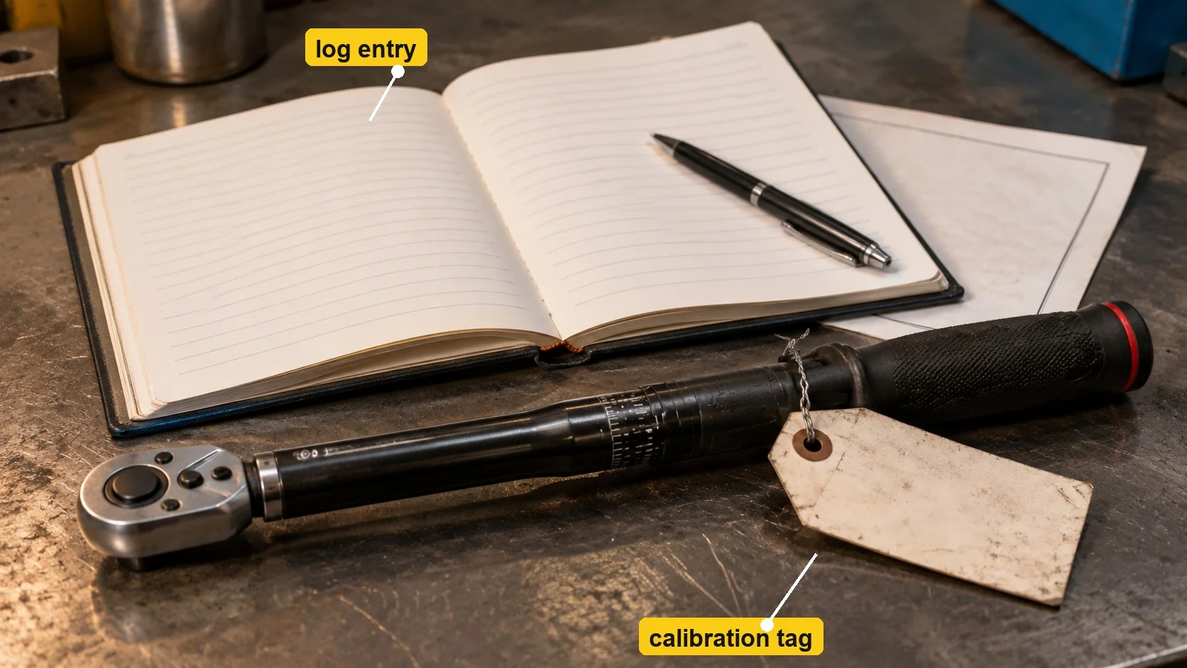
Torque records serve two different masters, and a good form satisfies both. The first is engineering: if a fitting fails in service, the record tells the investigator which tool, at what setting, on which date, by which operator, so the failure can be attributed to the fitting, the tool or the method instead of guessed at. The second is commercial: on transmission and industrial contracts, torque evidence per joint is frequently a contractual requirement for payment, and a crew that cannot produce it re-does the work.
A usable torque log does not need to be elaborate. It needs tool identity, calibration reference, the torque source document, the circuit and structure, the fitting type and position, the operator, and the date. Digital wrenches can export this directly; click wrenches rely on the operator, which is exactly why the log pairs with the calibration tag on the tool. Records live with the other site documentation — the same place as the inspection findings described in the line fittings inspection guide, so that a later inspection finding a suspect joint can be traced back to its installation record in one step.
One habit pays for itself: when a joint is re-opened for any reason, log the re-making of it as a new entry. A re-torqued joint is a new joint, and treating it as such keeps the record honest.
Common Field Errors and the Correct Practice
| Field error | What it causes | Correct practice |
|---|---|---|
| Wrench dropped from the pole, then used again without verification | Silent calibration shift; every subsequent joint is off-value with no visible sign | Remove from service, tag it, send for verification; use the spare calibrated wrench meanwhile |
| Extension pipe (“cheater bar”) on the handle to reach a high value | Uncontrolled torque far beyond the setting; yielded bolts and cracked castings | Use the correct range wrench or a powered torque tool rated for the joint |
| Target value near the bottom or top of the wrench’s scale | Poor accuracy at the extremes; result drifts from the intended clamping force | Move the job to a wrench whose range brackets the target in its middle portion |
| Click masked by gloves and wind; operator “pulls a bit more to be sure” | Over-torqued joint that looks perfectly installed | Slow steady pull, stop at the single click; re-verify the setting if the click was not clearly felt |
| Torque wrench used as the everyday ratchet for running bolts down | Accelerated mechanism wear and early calibration drift | Run down with a standard wrench; torque wrench only for the final measured turn |
| Setting taken from memory or from a similar fitting | Wrong value entirely — the most common root cause in bolted-fitting failures | Set only from the fitting’s specification sheet or the project specification, at the time of the job |
| Re-clicking an already-tightened joint | Unmeasured additional clamping force; conductor or casting damage | One click per joint; if a joint must be redone, back the nut off and re-torque as a new joint |
| No record of tool, setting, operator or date | Failure investigation impossible; contractual torque evidence missing | Log every torque-controlled joint, including re-made ones |
FAQ
How often should a line crew’s torque wrenches be calibrated?
At the interval stated by the tool manufacturer or the project specification, whichever is shorter — and always after any drop, overload or visible damage. There is no universal figure: the interval depends on the tool type, the duty cycle and the accuracy class stated on its certificate. When nothing is specified, agree an interval with your calibration laboratory and keep it in the tool procedure so the crew is never deciding it informally.
The wrench fell off the crossarm. It looks fine — can we keep using it?
No. A drop is an event, not an appearance question. The mechanism can shift without any visible mark, and a drifted wrench produces joints that are consistently wrong while looking normal. Tag it out of service, send it for verification, and continue with a spare calibrated wrench. Crews that carry a second calibrated wrench for exactly this reason lose no time to it.
Are digital torque wrenches worth it for line work?
They earn their place when per-joint torque evidence is required, because the stored readings feed the site records directly and target-value alarms stop over-pull mistakes. For routine distribution hardware where no such evidence is demanded, a maintained click-type wrench set from the fitting’s specification sheet does the same job at lower cost and with no battery. Many crews run both: click for volume, digital for joints that must be documented.
Can a torque wrench be used as a normal ratchet?
Only lightly. Running a bolt fully down under torque engagement hammers the release mechanism and shortens the calibration life dramatically. Use a standard ratchet or spanner for the run-down and bring the torque wrench in for the final measured pull. It is a measuring instrument with a drive end, not a drive tool that happens to click.
What should be written down for each torque-controlled joint?
The tool’s identification and its calibration reference, the torque value and where that value came from (the fitting’s specification sheet or the project specification), the circuit and structure, the fitting type and its position, the operator and the date. If the joint was re-made, log that as a new entry. Anything less turns a future failure investigation into guesswork.
Every torque figure quoted in this article’s practice — when to verify, how to set, what to record — follows one principle: the number itself always comes from the fitting manufacturer’s specification sheet or the project specification, never from habit. Crews that pair a calibrated tool with a written setting routine and an honest log get joints that hold; procurement teams that specify torque-class hardware and demand the records get projects they can defend. If a fitting’s torque data is missing or unclear before work starts, resolve it with the supplier first — that single habit prevents more bolted-joint failures than any tool upgrade.