Aeolian Vibration on Overhead Lines: Causes and Control
Aeolian vibration leaves almost no trace until someone opens a suspension clamp and finds the outer aluminium strands cut through. The conductor looks straight, the sag is correct, the clamps went on to drawing, and the line has been fatiguing itself for years at an amplitude of about one conductor diameter — movement nobody notices from the ground. By the time damage is visible from a bucket truck it is usually a repair job rather than a maintenance note.
That matters commercially. Vibration protection is the item most often deleted during value engineering, because it is invisible, cheap next to the conductor, and easy to call optional. The consequence appears three to eight years later at the clamp mouth. What follows covers the mechanism, the damage signature, the protection options, and how each is specified and inspected. It gives no tuning frequencies, installation distances or acceptance thresholds: those are calculated per line section and per conductor, and must come from the supplier’s calculation sheet and the project specification.
What Aeolian Vibration Actually Is
Wind crossing a conductor at a moderate angle sheds vortices alternately from its upper and lower surface, producing a small alternating force perpendicular to the wind. Shedding frequency rises with wind speed and falls with conductor diameter, and can be written as a Strouhal number times wind speed divided by diameter — for a smooth round conductor the Strouhal number sits close to 0.2, which is why a thin conductor sheds at a much higher frequency than a thick one in the same wind.
The conductor is also a stretched string, with natural frequencies set by span, tension and mass per unit length. Vibration becomes damaging when shedding frequency coincides with one of them: the conductor locks into a standing wave and the shedding frequency follows the conductor rather than the wind. That lock-in makes the phenomenon persistent — the wind need not be strong or steady, and a light laminar wind crossing an exposed valley is the classic condition.
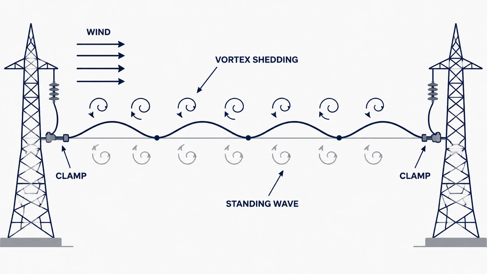
Three features drive every downstream decision. Amplitude is small — about one diameter — so this is not galloping and does not cause flashover. Frequency is high and cycles accumulate fast, so fatigue governs rather than strength. And bending strain concentrates where the conductor leaves a rigid body, which is why failures appear at the clamp and why vibration protection is a clamp-and-conductor problem.
Why the Damage Appears at the Clamp Mouth
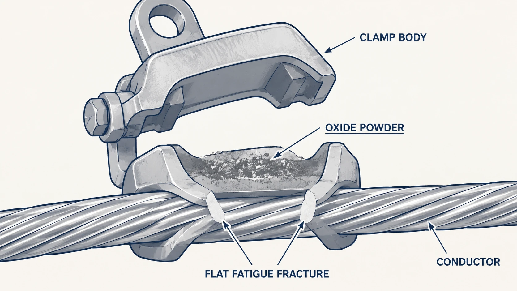
At mid-span the conductor bends freely, and the curvature of a loop of one-diameter amplitude is small. Where the conductor emerges from a suspension clamp, strain clamp or damper clamp it is effectively held against rotation. Bending stiffness changes abruptly from clamped to free, and alternating bending stress peaks within a short distance of the clamp mouth — typically the first few hundred millimetres, precisely the region inspection programmes skip because it sits under the clamp body and the armour rods.
The mechanism is fretting fatigue, not simple tension. Adjacent aluminium strands slide against each other by a fraction of a millimetre, many times per second. That micro-slip breaks the oxide film protecting the aluminium and generates fine black or grey oxide powder — often the first visible evidence, found inside the clamp body or under the rods long before a strand breaks. Once debris is present, load sharing between strands becomes uneven, and outer strands fail one at a time from the outside in.
Fatigue fractures look different from overload fractures, and the difference is worth teaching to inspectors. An overload break shows necking, a dull cup-and-cone face and often a birdcage of strands. A fatigue break in one aluminium strand is flat and bright, sometimes with faint beach marks, with no necking. When several strands at one clamp mouth show flat faces at slightly different positions, the cause is vibration rather than a one-off event.
The Variables That Decide Whether a Line Will Vibrate
Vibration is not a property of a conductor. It is a property of a conductor in a particular span, at a particular tension, in a particular exposure. Four variables dominate, and only some stay adjustable once a route is fixed.
| Variable | How it pushes the risk | Adjustable at specification stage? |
|---|---|---|
| Everyday tension relative to conductor weight | Higher tension raises natural frequencies and stiffens the string, reducing amplitude but sharply raising bending strain at the clamp for a given movement. Low-tension spans vibrate with larger amplitude; high-tension spans fail faster at the same amplitude. | Partly. Fixed by sag and clearance, so it follows the profile rather than being chosen freely. |
| Span length and terrain exposure | Long spans over open ground, water or a valley mouth see smoother, more laminar wind and have lower natural frequencies, both of which favour lock-in. Short spans inside a town or forest are largely shielded. | Yes, at route stage — tower spotting, span reduction, or a taller structure at an exposed crossing. |
| Wind angle to the line | Strongest with wind roughly perpendicular to the conductor. Winds within about thirty degrees of the line axis shed along the conductor instead of across it and produce little transverse excitation. | No, once built. A reason to check which spans cross the prevailing wind. |
| Conductor diameter and surface | Small diameters shed at high frequency and are the classic case. Large bundled conductors are less prone to aeolian vibration but introduce sub-span oscillation between spacers. | No. But it determines which hardware is appropriate. |
Protection is therefore decided per span group, not per project. A line running through farmland and then crossing an open estuary does not need the same treatment on both, and one damper type at one spacing across a whole route either overspends on the sheltered part or under-protects the crossing. Splitting the bill of quantities by exposure class is a normal request.
Reading the Symptoms in the Field
Most vibration damage is found by accident, during an unrelated outage, because the symptoms are subtle and the location awkward. A structured check looks for a small number of specific things, and separates what can be seen without opening anything from what requires the clamp to be opened.
| Symptom | What it indicates | How to confirm |
|---|---|---|
| Fine grey or black powder inside the clamp body, on the conductor under the rods, or on the bedding | Fretting between strands or between conductor and clamp. Early-stage vibration damage. | Open the clamp or lift the rods on a sample of structures. Photograph before cleaning. |
| Armour rods worn flat, displaced along the conductor, or with broken ends | Rods are absorbing vibration as intended but are fatigue-limited, or were the wrong diameter and have worked loose. | Measure rod position against the installation sheet; check for end clamps or binding wire. |
| Flat, bright fracture faces on outer strands just outside the clamp mouth | Established fatigue. The span is losing mechanical capacity. | Count broken strands per layer against the project repair criteria, not by eye. |
| Damper weight displaced, damper clamp loose, damper steel strand broken | Damper has slipped out of its tuned position or has itself fatigued. Protection is partly or wholly absent. | Measure clamp-to-damper distance against the installation sheet. |
| Conductor polished or darkened in a band a short distance from the clamp | Standing wave antinode close to the clamp. Suggests incorrect damper position or spacing. | Compare with neighbouring spans; one span behaving differently points to installation. |
Two cautions. A span can be badly fatigued with nothing visible from below, because the critical region sits under the clamp and the rods; the survey narrows the sample, it does not clear the line. And armour rods are not evidence of protection — they distribute pressure and resist wear but remove no strain. The wider method is in overhead line fittings inspection; failure modes often mistaken for vibration damage are in suspension clamp failure causes and field checks.
The Protection Options and What Each One Actually Does
No method stops the wind. Each either reduces the strain reaching the conductor or removes energy from the system, and the differences matter when a bill of quantities is written.
Armour rods and line guards
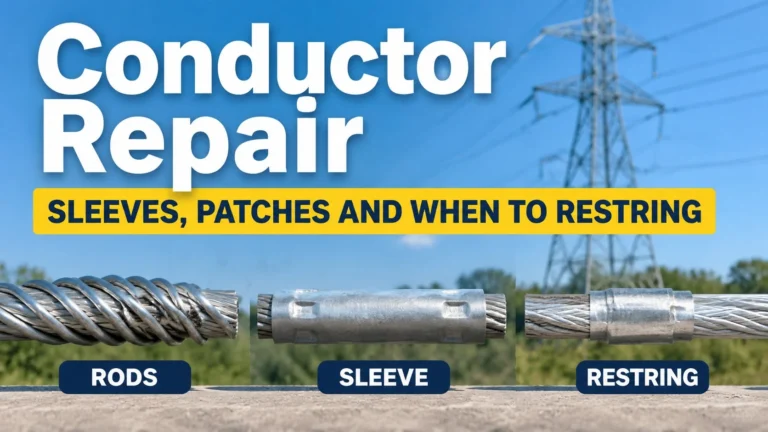
Preformed rods wrapped around the conductor spread clamping pressure over a longer length, add local stiffness so bending strain is distributed along the rod instead of concentrating at the clamp mouth, and take the wear that would otherwise sit on the conductor. They are a strain-distribution measure, not a damper, and they only work if the rod diameter matches the conductor and the length matches the calculation. Rod ends must be terminated as the manufacturer requires, or the last few centimetres work loose. The assembly detail is in the suspension clamp installation guide.
Stockbridge dampers
Two masses on a short length of stranded steel cable, clamped to the conductor. When the conductor moves the masses lag and the strand flexes, dissipating energy as heat. It is tuned — its resonant frequencies sit where the span vibrates — and tuning is useless if the damper is in the wrong place. A damper at the wrong distance can be worse than none, because it may convert a high-frequency, low-amplitude mode into a lower-frequency mode with larger amplitude at the clamp. Position comes from the supplier’s calculation for that span.
Spiral vibration dampers
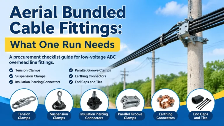
Helical plastic or metal elements wound onto the conductor dissipate energy through friction between helix and conductor and between adjacent turns. Compact, no separate clamp, common on smaller conductors, insulated aerial bundled cable and optical cable where a bolted damper is awkward or allowed clamping pressure is low. On bundled and optical work the constraint set differs again — see aerial bundled cable fittings and the ADSS notes on suspension clamps for ADSS cable support.
Damping wire and loop dampers
Short lengths of conductor or wire looped at the clamp, used mainly on short spans at substation exits and on jumpers where a conventional damper has nowhere useful to sit. Inexpensive and effective in the band they cover, but frequently installed with no calculation, which is why their reputation is mixed.
Spacers and spacer dampers on bundles
On bundles the dominant movement is not the aeolian vibration of a single conductor but relative motion of sub-conductors between spacers, plus wake-induced oscillation. Spacers hold bundle geometry; spacer dampers add dissipation. Neither substitutes for conductor-level protection at the clamp, and a well-spaced bundle with bare suspension clamps is still exposed.
Reducing everyday tension, and route measures
Lower everyday tension lowers natural frequencies and reduces strain amplitude at the clamp. It costs sag, and sag costs tower height or clearance, so it is a design-stage decision rather than a retrofit. Where one span is the problem, the honest options are structural — an intermediate tower, a different crossing point, or accepting annual inspection.
| Protection item | Mechanism | Best suited to | Common specification error |
|---|---|---|---|
| Armour rods / line guards | Distributes clamping pressure and bending strain along the rod length; sacrificial wear surface | Suspension and strain clamps on conductors where the groove can damage strands | Rods ordered by length only, without conductor diameter and without end termination |
| Stockbridge damper | Tuned mass on a flexing steel strand; dissipates energy over a frequency band | Medium and long spans on exposed terrain, bare overhead conductor | Position and quantity not taken from a span-by-span calculation sheet |
| Spiral vibration damper | Friction between helix and conductor; no bolted clamp | Small conductors, ABC, optical cable, low allowed clamping pressure | Selected by conductor diameter alone, without wind speed or span data |
| Damping wire / loop | Added mass and local damping at the termination | Short spans, substation exits, jumpers | Installed as a habit with no calculation and no record |
| Spacer / spacer damper | Holds bundle geometry; damper version adds dissipation between sub-conductors | Bundled conductors, sub-span oscillation control | Treated as a substitute for conductor protection at the clamp |
Selecting a Damper: What the Specification Must Fix
An enquiry reading “Stockbridge damper, quantity 400 sets” cannot be answered properly, because the two things deciding whether the hardware works — tuning and position — depend on data the supplier does not have. A usable enquiry contains the following, and a supplier who does not ask for them is guessing.
- Conductor data: designation, nominal and actual diameter, stranding, mass per unit length, calculated breaking load. Diameter alone is not enough for a damper clamp; the groove must match the outer layer.
- Span data: representative, maximum and minimum span, and the number of spans in each exposure group. Quantity per span follows from this, not from a per-kilometre rate.
- Tension, sag and wind: everyday tension or the stringing sag-tension table, design temperature range, design wind speed and prevailing direction relative to the line.
- Attachment and environment: suspension string length, clamp model, whether armour rods form part of the assembly (the damper sits outboard of the rods, so both must be dimensioned together), and whether the site is coastal, industrial or clean, since the damper body, clamp bolt and steel strand are where dampers fail first in aggressive atmospheres.
- Documentation: a span-by-span installation sheet giving distance from the clamp and quantity, plus the type or fatigue test reports the project requires. Ask for these as deliverables of the order, not as a favour after it.
The cost of getting this wrong is asymmetric. A damper set is a small fraction of line cost; re-conductoring fifteen spans is not. The general framework for a fitting enquiry is in how to specify overhead line fittings in an RFQ, and it applies to vibration hardware as much as to clamps.
Installation Position and Spacing: Why the Number Comes From a Calculation
Vibration produces a standing wave with nodes at fixed points. A damper works by sitting near a node, where conductor movement is small but the damper’s own response can be excited; the distance is a fraction of the wavelength of the mode being controlled, and differs between first, second and third modes. That is why the position cannot be one standard dimension applied to every line, and why two suppliers quoting the same offset for different conductors are both probably wrong for one of them.
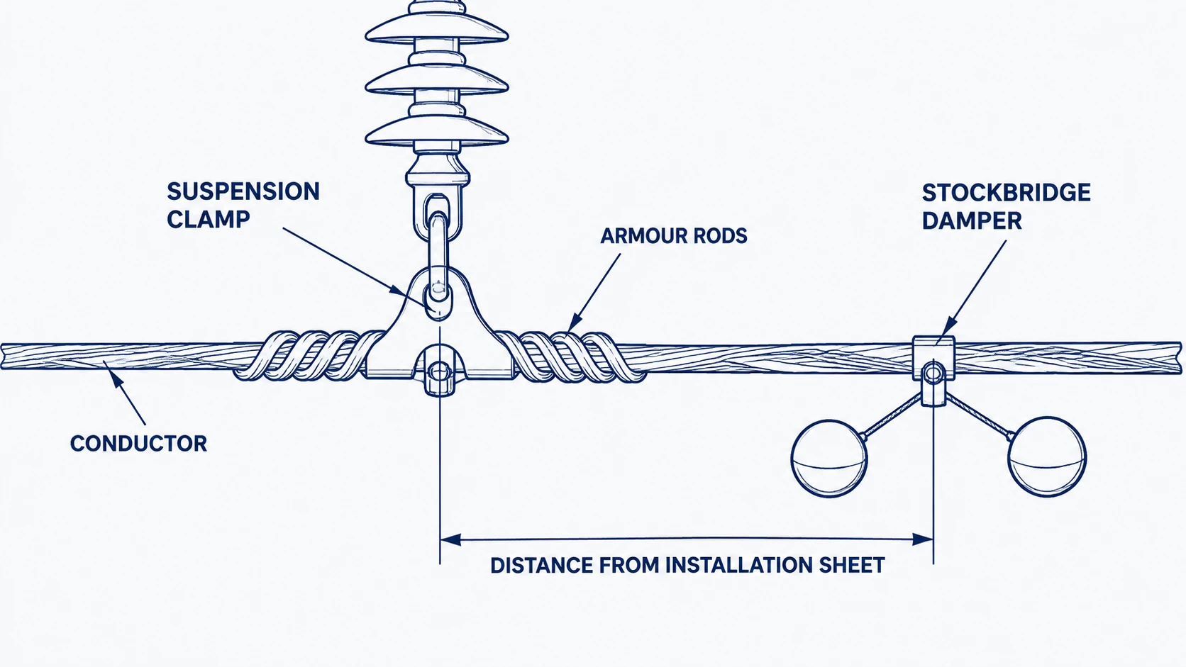
The rules that hold are procedural. Measure from the reference point the sheet names — clamp centre or the end of the rod set — not from whatever edge is convenient, and mark the position before fitting so the crew can verify it after the clamp closes. Keep damper clamp bolt orientation consistent, since a bolt head bearing on the conductor is a wear and corona problem. Never hang tools from a damper: the steel strand is the tuned element. Where a damper must be moved, inspect the conductor under the old position. On strain assemblies the same logic applies at the other end of the span — see the tension clamp installation guide.
Count per span deserves the same discipline. Multiple dampers are normal on long spans and their spacing is part of the calculation; one damper where the sheet calls for two leaves the span half-protected, and failure appears at the clamp left out.
Acceptance, Storage and the Handover Record
Vibration hardware is easy to damage before installation: damper strands kink if a carton is dropped, preformed rods deform under a pallet, spiral dampers take a permanent set if coiled too tightly. Receiving inspection should check the tuned element, not just the castings — strand for kinks and broken wires, mass for movement, clamp groove for the correct conductor size marking, finish for transit damage — as set out in incoming inspection of line hardware. The handover record then matters more than usual, because the protection is invisible in service: per structure and phase, the damper model, measured distance, number fitted, rod length and date.
Inspection Over the Service Life
Damage accumulates in seasons of steady moderate wind, so the first meaningful inspection falls after the first full windy season rather than at commissioning. A workable programme covers the clamp mouth region on a sample of structures, the position and condition of every damper, and the rod ends. Ground survey with binoculars finds displaced dampers and broken lower-layer strands; a bucket or drone finds powder, wear and flat fracture faces. Opening the clamp on a small sample is the only way to see the conductor under the bedding.
Replacement criteria come from the project specification and the conductor repair rules. The direction of the decision can be stated: broken outer strands beyond the permitted count mean repair or replacement, a slipped damper means repositioning plus inspection of the exposed conductor, and several spans showing the same symptom at the same clamp type mean the protection scheme needs recalculating. Grip and slip behaviour of the clamp itself, often confused with vibration damage, is measured separately — see suspension clamp grip strength and slip test.
Frequently Asked Questions
How do I know whether a line needs vibration protection?
It is a calculation, not a judgement call. Inputs are conductor diameter and mass, everyday tension, span lengths, terrain exposure and design wind speed; the output is whether the span falls into a regime where aeolian vibration produces damaging strain at the clamp. Ask the supplier or design institute to run it per span group and state the assumption set. Exposed spans over open ground or water, and spans run close to design tension, are the ones to check first.
Can dampers be installed on a line that is already energized?
It is done, using live-line techniques or a planned outage, and that is a safety and cost decision rather than a technical one. Two technical points apply. The conductor under the new position has to be inspected before the damper goes on, because that region has been unprotected. And a retrofit is the moment to fix quantity and spacing from a calculation instead of repeating whatever the neighbouring span has.
Do armour rods alone stop aeolian vibration?
No. They reduce the bending strain reaching the conductor and protect it from wear and clamping pressure, which is why they are fitted almost everywhere, but they remove no energy from the system. A span with rods and no damper can still fatigue — more slowly, over a longer length. Rods and dampers solve different halves of the problem.
Why do dampers sometimes seem to make vibration worse?
Almost always position or quantity. A damper placed away from its designed location can shift the span into a lower-frequency mode with larger amplitude at the clamp, and a single damper on a span that needed two leaves an unprotected region. A damper with a broken steel strand, or one whose clamp has slipped, behaves the same way. Before blaming the hardware, measure what is installed against the installation sheet.
Vibration protection is cheap, unglamorous and easy to defer, which is exactly why it gets deferred. The decision that protects a line is made at enquiry stage, while conductor and span data are still being assembled. Buyers who specify per exposure group, insist on an installation sheet with measured distances and record what was fitted get spans that survive their first decade. Those who buy dampers by the set and fit them by eye find out at the clamp mouth. For the assemblies these components sit on, see the suspension clamp supplier page.