How to Install a Suspension Clamp: Conductor Seating, Torque and Armor Rods
Suspension clamp installation gets about fifteen minutes of attention on a stringing job, and then carries the weight of the span for decades. When one of these fittings causes trouble later, the cause is usually in that quarter of an hour: the conductor walking through the body, the strands breaking at the keeper edge, the U-bolts found slack on patrol. This guide covers the installation itself: conductor seating, what goes between conductor and clamp, U-bolt torque and sequence, how far the line may deviate at a tangent structure, and what to check before the crew comes down. Selection, failure diagnosis and grip testing each have their own write-up, linked rather than repeated here.
What suspension clamp installation has to get right
The procedure serves three outcomes that pull against each other.
- The interface has to hold. It must resist the conductor being pulled lengthwise under normal load and under unbalanced load — ice off one span, broken conductor on the next.
- The conductor must survive it. Crushed or nicked strands are permanent loss of section where bending stress is highest.
- The assembly must stay free to move. A tangent clamp lets the conductor swing slightly under wind and thermal expansion; a rigid pivot moves the problem into the conductor.
Pressure is the lever you control, and it cuts both ways. Too little and the conductor creeps; too much and you have done the damage yourself before the line is energised. Torque is how that pressure is set, and it is set by measurement, not feel.
Two preconditions come before any of it. The clamp sits where the drawing says, which means plumbing the suspension point rather than guessing it. And its parts belong to one design — body, keeper, U-bolts, washers and locking devices together. Hardware that looks interchangeable between similar models often is not.
Checks to finish before the clamp goes on the conductor
This guide starts where the conductor size and clamp model are already settled against the drawing. If that decision is still open, how a suspension clamp is chosen covers it — nothing below rescues a clamp that was never sized for the conductor.
- Measure the real conductor. Caliper it at the structure, not the nominal diameter off the stringing table. Birdcaging, ovality after tensioning and manufacturing tolerance all shift the figure the clamp’s range was written against.
- Check every part is present and undamaged. Count nuts, washers, lock washers and split pins against the drawing, and look for bent U-bolts, damaged threads, cracked castings and deformed keepers. Transit damage is far cheaper to see on the ground.
- Bring a torque wrench that covers the target value in the middle of its scale , with a valid calibration date. A wrench used at either end of its scale is inaccurate in exactly the way that matters here.
- Clean the contact length. Grit, oxidation and old compound become a permanent fretting site.
- Decide what goes between conductor and clamp — tape, armor rods, or nothing — before the conductor is in the groove.
Marking the conductor and seating it in the groove
Plumb the suspension point and bring the mark onto the conductor with a felt pen or lumber crayon. Never notch the conductor or the armor rods to make a reference mark — even a shallow nick in an outer strand is a fatigue starter at the clamp mouth.
Open the clamp fully: lift the keeper out rather than prising it loose, and run the U-bolt nuts back far enough that nothing is forced. A clamp assembled half-open tends to trap one strand outside the groove, and once it is under torque nobody sees it.
Seat the conductor in the bottom of the groove over its full contact length, then check three things from both sides:
- No strand, and no part of the cross-section, is riding on the keeper edge.
- The conductor lies along the clamp axis, with no twist or kink immediately either side.
- Your centre mark is where the clamp body falls, so the keeper lands square.
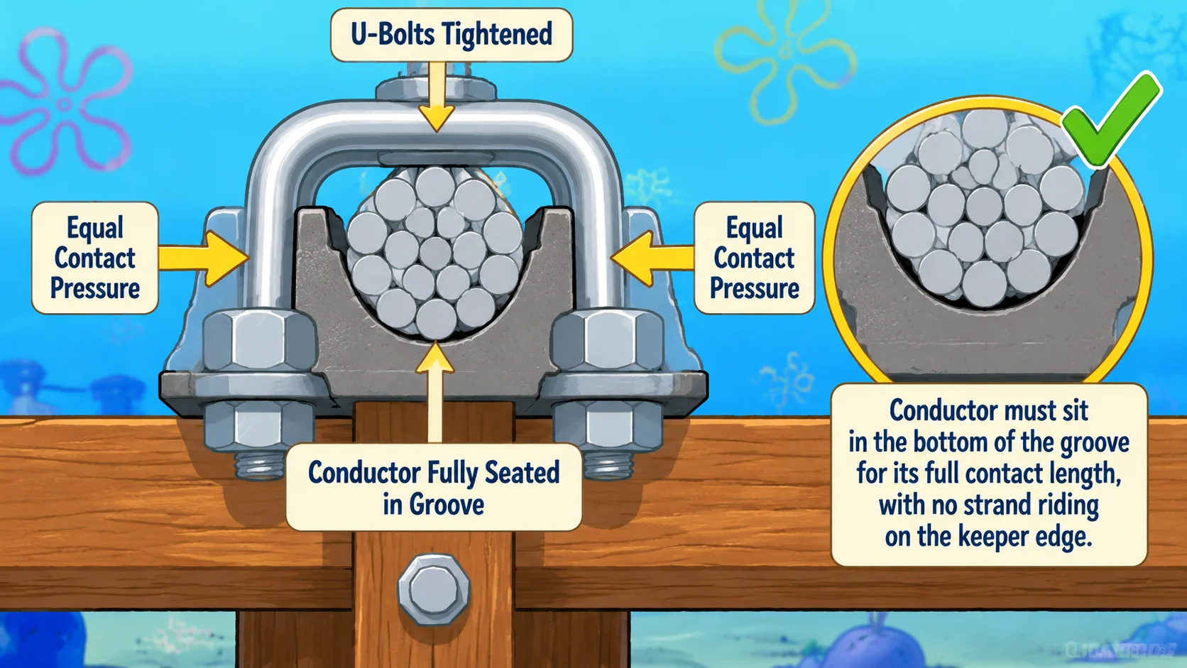
Partial seating has the longest fuse. If any part of the conductor rests on the keeper edge, contact area drops, pressure concentrates along one line and the strands flatten at the clamp exit. The line can enter service looking fine and lose strands there years later.
Aluminium tape or armor rods: deciding what goes under the clamp
On bare aluminium-strand conductors — ACSR, AAC, AAAC — something normally sits between conductor and metal body. There are two common answers, and they are alternatives rather than layers.
| Approach | What it is | Where it applies | Installation point |
|---|---|---|---|
| Aluminium tape wrap | Measured aluminium banding wound onto the conductor over the clamp contact length | Routine on aluminium-strand conductors | Wrap direction follows the outer strand lay; centred on the clamp centre mark |
| Preformed armor rod set | Factory-formed set of helical aluminium alloy rods | High vibration exposure, long spans, partly damaged conductor | Sized by diameter range and lay direction; replaces the tape requirement |
| Bare cable in an elastomer-lined body | No added layer; resilient liner in the body | ADSS and some OPGW sets; polymer-bodied distribution clamps | Over-tightening damages the cable inside before the hardware shows anything |
Where preformed protection is specified, the tape is normally not required as well. Your project’s process card governs, and stacking both is worse than picking one: tape under a rod set changes the built-up diameter the set was sized for.
On the tape itself, wrap direction must follow the lay of the outer aluminium strands, tight and turn against turn, centred on the clamp centre mark. Most crews start at the centre and work outward, leaving both ends to be folded back under the body. How far the tape may project beyond the clamp mouth is the project’s number to give — often a maximum of around 10 mm in construction process documents, not transferable between specifications.
Installing armor rods: lay direction, centring and single-use handling
Armor rods do two things here: they spread the bending strain that concentrates at the keeper edge over a longer length, and they take the wear so movement rubs against replaceable rods rather than strands. Both depend on the set being the right set and going on the right way round.
Size against measured diameter, not conductor name. A set marked for a diameter window covers any conductor inside it, and makers colour-code rod ends so crews can identify the window without a caliper — adjacent sizes differ by fractions of a millimetre.
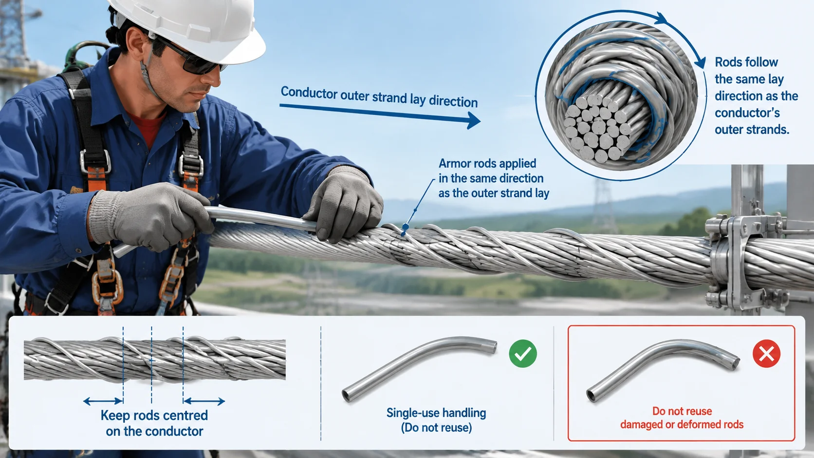
Lay direction has to be read off the conductor first. Preformed rods are wound to a helix and that helix has a hand to it: note which way the outer strands spiral away from your eye and match it. Get it wrong and the rods cross the strands instead of bedding into them. Grip never develops, the set can work its way along the conductor under vibration, and the only remedy is cutting it off and starting again — it is the one armor rod defect that cannot be corrected afterwards.
- Clean the conductor over the full rod length.
- Mark the clamp centre position and centre the set on it. Applying the marked centre rod first and working outward, alternating sides, keeps the distribution even.
- Seat each rod by hand pressure rather than sliding it along the conductor.
- Space the rod ends evenly round the circumference — uneven spacing is the main cause of uneven clamping later.
- Twist the rods on in the lay direction. Rolling tools buy consistency; hand application works.
Inspect the finished set in three places: rod ends evenly spaced, nothing crossing at the centre, no gap between rods and conductor at the clamp position. A set that clears all three and still rotates by hand usually means the diameter window was wrong.
Two things the paperwork tends to lose. Armor rods are single use — elastic deformation produces the grip, and it does not come back. And the clamp has to be sized for the built-up diameter over the rods, not the bare conductor. It is the same helical grip principle explained in preformed dead-end grips for guy wires.
Tightening sequence and torque for suspension clamp installation
Fit the keeper, pass the U-bolts, fit washers and nuts in the drawing’s sequence, and tighten by hand until snug. That is not a nicety: while the nuts are loose the clamp can still settle square, and once one bolt is pulling hard nothing settles anywhere.
Then bring the nuts up in a circular or diagonal pattern, only part of the way each pass — start with any bolt, tighten partially, move to the next, repeat until the specified value is reached on all of them. Taking one U-bolt to full torque first cants the keeper, loads one side of the body and leaves the rest carrying nothing, while the wrench still reports a pass.
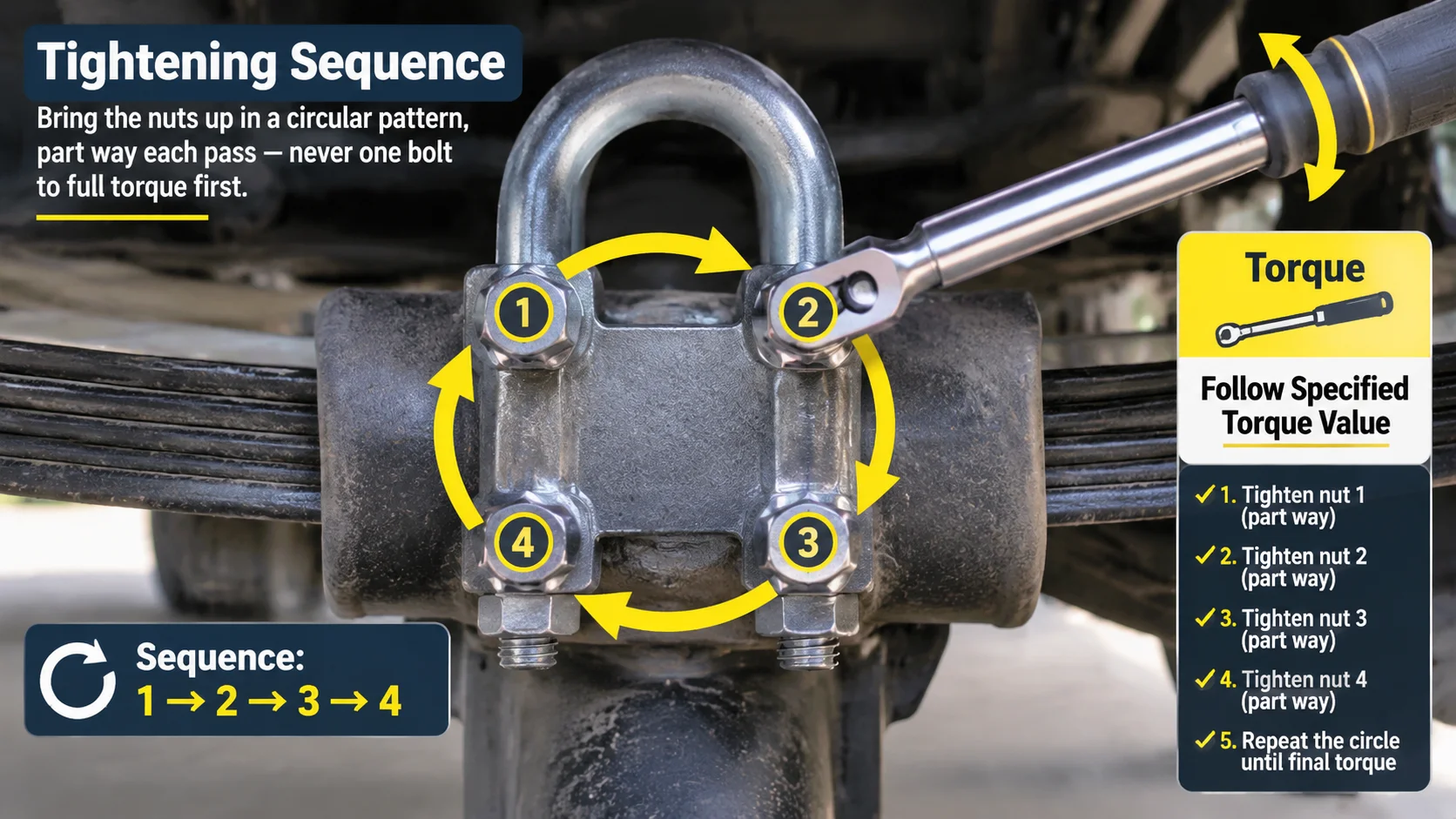
The final value comes from the drawing or torque table for that model. There is no general figure. It depends on bolt diameter and grade, clamp size range, whether there is a resilient liner, and whether the threads are dry, plated or lubricated.
How wide that spread runs is the part crews underestimate. The torque written for a small distribution clamp and the torque for a large bundle-conductor clamp are not variations on a theme — they differ by multiples, and the difference comes from exactly the variables listed above. A value carried over from the last job, or from a different model in the same catalogue, is not a conservative approximation. It is simply the wrong number, and both directions of wrong are destructive: too low and the conductor creeps, too high and the strands are crushed before the line is energised.
So there is one usable source, and it is model-specific. The specification table for the model being installed carries its own conductor range and its own torque figure, and that figure — not a rule of thumb, not a borrowed value — is what goes on the wrench. If no torque figure came with the clamp, get one before anyone climbs: suppliers list it per model, and our own suspension clamp range grouped by conductor diameter is where those model-level figures sit.
Over-torque crushes the strands, extrudes the liner out of a resilient body and leaves a stress riser at the keeper edge — the wrench will not tell you when it happened. Under-torque lets the conductor move lengthways, and unbalanced loading is what brings that to the surface, so a slack clamp often survives commissioning and gives trouble in the first ice event. What the grip figure behind this is measured against is set out in what the slip test proves.
One more step that is easy to drop: once the last nut is at value, go back and re-check the earlier ones. Taking up one U-bolt relaxes the nuts already done.
Line angle and deflection: where a suspension clamp stops being adequate
A tangent suspension clamp is designed around a vertical load and a small angular deviation — not for holding a line round a corner.
At significant angle the horizontal component of conductor tension bears sideways. Body, keeper and shackle load in a direction they were not qualified for, and the joint becomes a hard pivot rather than a damped support. Wind-driven movement then works the conductor against the keeper edge instead of being absorbed.
There is no universal angle figure. Each assembly has its own qualified range, stated by its maker; each project states the limits it accepts, the permitted deviation of the insulator string among them. Both come off the drawing. If the angle exceeds what the suspension set is qualified for, the fix is design-side — a double suspension set, or tension hardware rated for that angle. Where that boundary falls is covered in the suspension and tension clamp comparison.
Stated plainly, because it is a tempting shortcut on site: tightening past the specified torque buys no extra angular capacity. It buys a crushed conductor and a rigid joint, which is the combination that fails soonest.
Checks to run before the crew leaves the structure
Everything here costs a couple of minutes while the tools are out, and far more once the crew is back on the ground:
- Torque re-checked on every U-bolt nut, going round them again.
- Thread protrusion equal on each side of every U-bolt — a fast proxy for a keeper that came up square.
- Washers, lock washers, nuts and split pins present and seated. Where the spec calls for a lock washer to be flattened, it should be flat; every cotter opened.
- No visible gap between body and conductor along the contact length, no strand outside the groove.
- Body level, not twisted , insulator string plumb within the project’s permitted deviation.
- No conductor damage from the work itself — scrapes, tool marks or flattened outer strands.
- A witness line across nut and body if the maintenance practice uses one.
Record three things against the structure ID: clamp model, torque used, and whether tape or rods went under it. Those notes are what let someone judge a similar clamp on the same line later. What each symptom means in service is dealt with in suspension clamp failure causes and field checks.
Installation mistakes and the damage each one causes
These repeat across crews because each looks harmless at the time.
| Mistake on site | What it does |
|---|---|
| Conductor riding partly on the keeper edge | Pressure concentrates on a line, strands flatten at the clamp exit, breakage years later. |
| Mixing body, keeper or U-bolts from different models | Groove radius and keeper profile no longer match; even torque gives unpredictable grip. |
| One bolt taken to full torque before the others | Keeper canted, remaining bolts carrying little, wrench still reports a pass. |
| Tightening by feel | No repeatability between crews, usually surfacing as both failure modes on one line. |
| Rods applied against the conductor lay direction | They ride over the strands; grip never develops, the set walks and must be scrapped. |
| Tape or rod set not centred on the clamp centre mark | Protection stops short on the loaded side; wear resumes where it was meant to stop. |
| Reusing an armor rod set, even one never loaded | Elastic deformation already spent; no full grip a second time. |
| Skipping conductor cleaning on an existing line | Grit under the protection layer frets against the strands permanently. |
| Tangent suspension set at a real line angle | Sideways loading it was never qualified for; a pivot where a damped support was designed. |
| Over-tightening an ADSS or OPGW set | The cable is damaged before the hardware shows anything. Crush limits for optical cable are far tighter than for conductors; see ADSS cable suspension support hardware. |
Frequently asked questions
Do I need a torque wrench for suspension clamp installation?
Yes. Feel-based tightening gives no repeatability between crew members, and this is the one setting that decides both grip and conductor damage. Use a wrench that covers the target value in the middle of its scale, calibration date checked. If the clamp came without a torque figure, get one first.
What U-bolt torque should I use?
The figure the manufacturer states for that model, from the drawing or the table shipped with it. It varies with bolt size and grade, the clamp’s conductor range, whether the body carries a resilient liner, and thread condition — there is no safe generic value. The spread between a small distribution clamp and a large one runs to multiples rather than a few percent, so use the value in the specification table for the model you are fitting, never one carried over from a previous job.
Do I need both aluminium tape and armor rods?
Usually one or the other, and the choice belongs to the specification rather than the crew. Where preformed protection is specified it normally satisfies the tape requirement. Layering both is worse than choosing, because tape changes the built-up diameter the rod set was sized for.
Can armor rods be removed and reinstalled?
No. The grip comes from elastic deformation, spent once the set has been applied. A removed set goes in the scrap bag — including one wound the wrong way.
How much line angle can a suspension clamp take?
Whatever angular deviation its maker qualified the assembly for, and whatever permitted offset the project sets for the insulator string. Past that limit the answer is different hardware — a double suspension arrangement or tension fittings rated for the angle — not a tighter clamp.
What should a correctly installed clamp look like afterwards?
Keeper square and level, contact along the full groove length, no strand outside the body, equal thread protrusion on each U-bolt, all locking hardware present and seated, and no deformation where the conductor leaves the clamp. Then re-check torque once more.
Three numbers are worth writing down before anyone climbs: the diameter you measured, the lay direction you read off those strands, and the torque figure for the model going on. Most suspension clamp problems are one of those three assumed instead of checked.