How to Read a Cable Lug Specification Sheet
Every cable lug catalog page looks friendly until you actually have to order from it. A grid of part numbers, a column of conductor sizes, a stud dimension, a plating note — and somewhere a crimping chart that lives on a different page. Buyers who read only the part number and the biggest number in the size column end up with lugs that fit the cable but not the stud, or fit both but cannot be crimped with the tools the crew already owns. The specification sheet is where all of those mismatches can be caught, before the parts are packed and shipped, and long before anyone climbs a pole with them.
This article walks through a cable lug specification sheet the way an experienced buyer reads it: column by column, in the order the consequences matter. It is written for purchasing and engineering staff at utilities, contractors, panel builders and distributors — people who need to compare offers from different factories and know exactly what they are agreeing to. If you are still deciding which family of lugs your project needs, start with our overview of cable lug types; this article assumes the type is settled and focuses on the data sheet itself.
What the Specification Sheet Is Actually Promising
A specification sheet is not marketing. It is the manufacturer’s written commitment about what a specific part number will do: which conductors it accepts, what bolt it fits, how it must be crimped, and what performance category it was designed and tested for. When two offers look identical in a photo but differ on one row of the sheet — barrel length, plating, the conductor class they accept — they are different products, and one of them may be wrong for your job.
That is why the sheet, not the product photo, should drive the RFQ. A photo cannot tell you whether the barrel accepts flexible Class 5 conductors or only stranded ones, or whether the temperature-rise column refers to the joint itself or to the conductor. The sheet can — provided you know which questions each column answers, and which questions it silently does not. This habit also makes supplier quotations comparable: when you ask bidders to quote against the same field list, deviations surface line by line instead of hiding in generic brochure text.
Start With the Conductor Columns — Not the Part Number
The most expensive misreadings on a lug datasheet happen in the first two columns, because buyers assume they mean something narrower than they do.
The Size Range Is a Range, Not One Number
Cable lugs are marked with a conductor cross-section — the number stamped on the palm or printed in the order code — but the specification sheet almost always lists an accepted range around it. The reason is mechanical: a crimped joint works by deforming the barrel around the conductor, and the barrel only deforms correctly if the conductor fills a defined share of it. Undersized conductors leave voids and give a joint with poor pull-out strength; oversized conductors overstress the barrel or simply do not enter.
So the column to read is the range, and the question to ask is whether your actual conductor sits comfortably inside it or at an edge. A conductor at the very edge of the accepted range can still pass a bench test but behave differently in production, where strand lay, insulation tolerance and conductor compactness vary. If your project uses compacted or filled conductors, confirm that the stated range applies to that construction too — this is exactly the kind of detail the supplier should confirm in writing, in the same way you would pin down any other parameter when you specify overhead line fittings in an RFQ.
Conductor Class and Type
Next to the size range, most sheets state which conductor constructions the lug accepts: stranded, flexible (fine-stranded), solid, or sector-shaped. This column quietly excludes more projects than any other, because flexible and fine-stranded conductors behave very differently in a compression barrel from ordinary stranded ones. A lug designed for Class 2 stranded conductors may accept a flexible Class 5 conductor of the same cross-section physically — the strands fit in — while giving a joint that fails the pull-out requirement, because fine strands need different deformation and often different crimp geometry.
Sector-shaped and compacted conductors add another layer: their effective outer diameter differs from a round conductor of the same cross-section, which affects both insertion and the crimp result. If your conductor is anything other than plain round stranded, treat the conductor-type column as mandatory reading, and ask the manufacturer to confirm the combination explicitly rather than assuming the size match settles it.
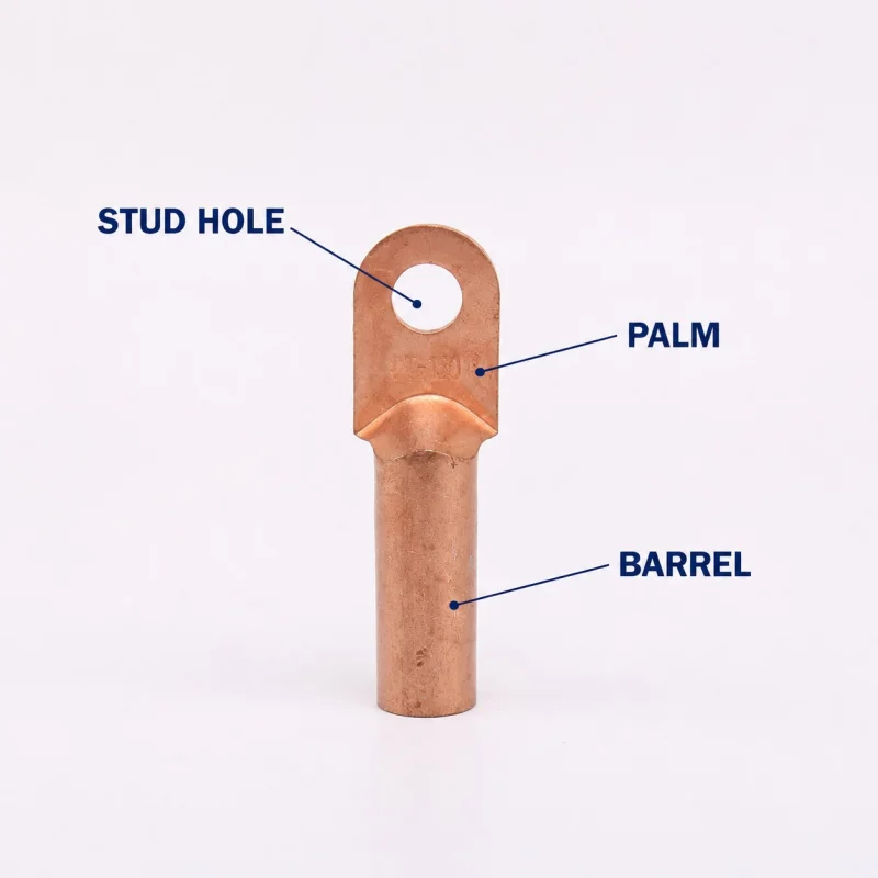
The Palm Side: Stud Hole and Palm Dimensions
Turn the sheet’s attention to the other end of the lug and read the palm data as a group, because its rows answer different questions than buyers usually ask.
The stud hole diameter is the obvious one: it must match the equipment bolt, not approximately but as a fit. Read the stated value together with the palm width and palm thickness, which determine whether the palm can carry the joint’s current and mechanical load without deforming, and whether it will clear nearby live parts and enclosures. Two lugs can share the same stud hole while having very different palm dimensions — and therefore very different behavior on a busbar with limited spacing.
Watch for two details that are easy to miss. First, some sheets list hole diameter as a nominal bolt designation while others list actual hole size; the two differ, and the difference matters when the drawing is used for clearance checks. Second, check whether the sheet states chamfers or countersinks on the hole — relevant when the lug lands on a stud with a washer train and specific seating requirements. None of these rows is exotic; they are simply skipped when a buyer matches the headline size and stops reading. The result is a part that bolts on but does not seat flat, or a palm that fouls adjacent phases inside a box.
The Barrel: Length, Wall, Chamfer and Inspection Window
The barrel rows describe how the joint is actually made, and they deserve the same slow reading as the conductor columns.
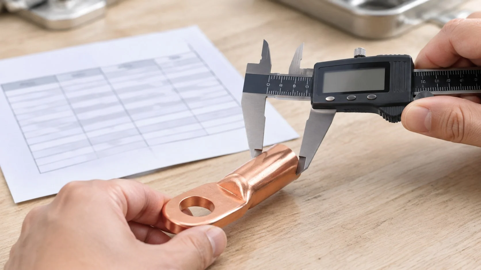
Barrel length sets how many crimp positions fit and how much conductor must be inserted — too short a barrel for the required crimp pattern and the joint is under-designed no matter how careful the crew is. Wall thickness determines the deformation behavior during crimping; this is why two lugs with the same outside diameter are not interchangeable between different tooling systems. The entry chamfer at the barrel mouth decides whether strands gather cleanly as the conductor enters or whether individual strands catch and fold back — a classic cause of hidden defects that pass visual inspection.
Many copper tube lugs include an inspection hole in the barrel. Read its role correctly: it is a go/no-go window to verify that the conductor is fully inserted before crimping, not a general-purpose viewing port, and its presence should be confirmed in the sheet if your work instructions rely on it. If the barrel rows on a supplier’s sheet are blank or marked “on request,” treat that as a question to resolve before ordering, not as a detail to discover on site. The crimping guide explains how these barrel features interact with tooling in practice — see cable lug crimping for the process side.
Plating: Bare Copper or Tinned — and What the Sheet Tells You About It
The plating row looks like a finish note but is a compatibility decision. Bare copper lugs are the default for copper conductors landing on copper or plated busbars in dry, non-corrosive environments. Tinned lugs add a layer that slows surface oxidation and is generally preferred where humidity, salt or frequent re-termination are expected, and where the lug will be paired with aluminum hardware in ways that make surface condition critical.
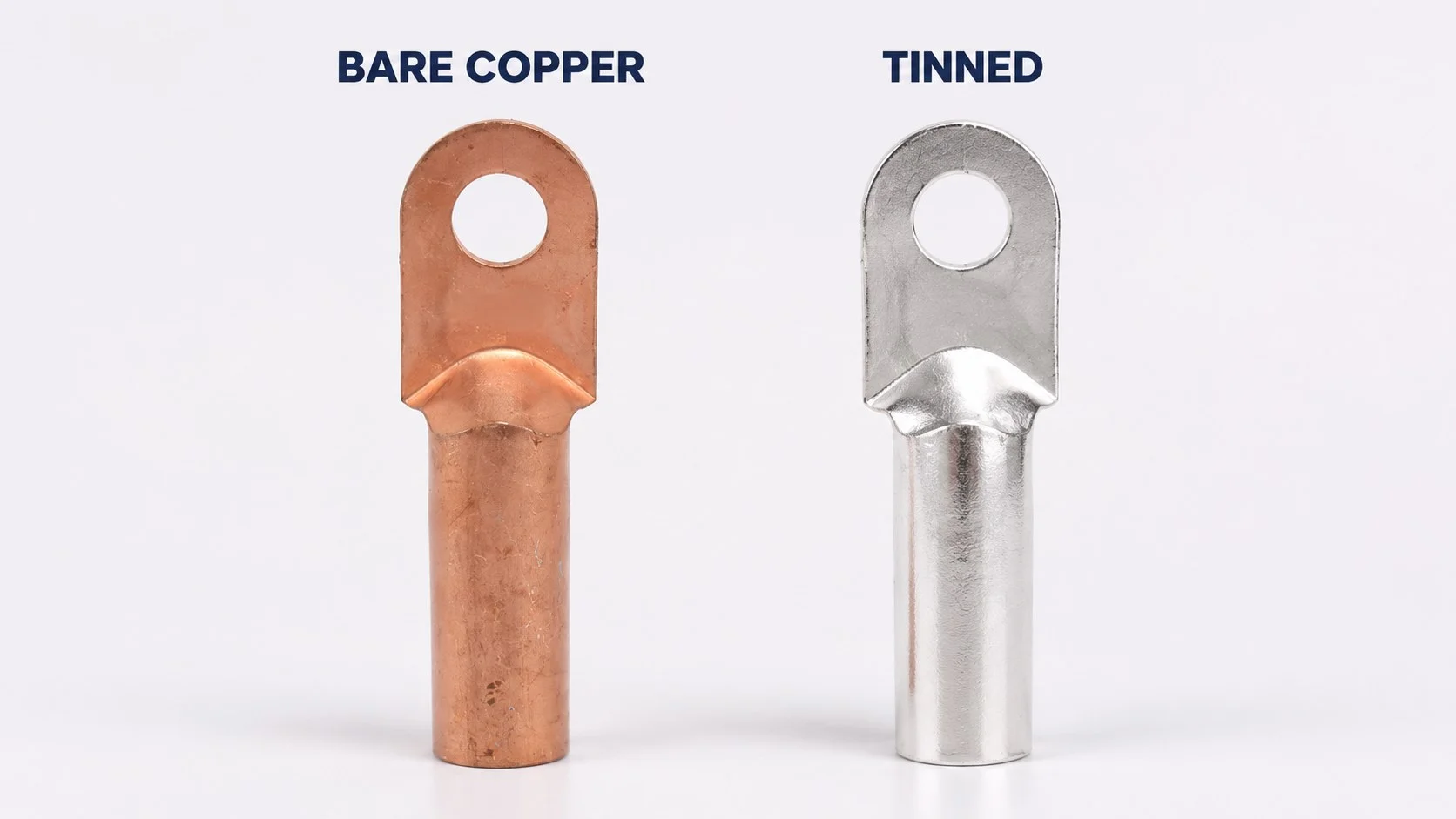
The sheet’s plating row also carries a marking function: tin plating changes the appearance of the stamped size marking and, in some ranges, the ordering code itself. When comparing quotations, confirm that both suppliers mean the same plating on the same code — cross-reading a bare-copper price against a tinned specification is a common quoting error. For the deeper metallurgical question of pairing copper lugs with aluminum conductors, and why a plain copper lug is not that answer, our comparison of copper vs aluminum cable lugs and the guide to bimetallic cable lugs cover the transition problems in detail; the datasheet’s plating row is only the first half of that decision.
The Crimping Columns: Die, Position and Count
If the sheet includes crimping data, this is the section that turns a dimension table into a work instruction — and the section most often ignored at quotation stage.
Read three things. First, the die reference: which crimping die or tool family the manufacturer’s data applies to. Die geometry is not universal across brands, so a joint made with an unlisted die falls outside the tested configuration even if the crimp looks correct. Second, the crimp position: where along the barrel each indentation should sit. Third, the number of crimps: some configurations call for one impression on smaller barrels and multiple impressions on larger ones, and the sheet is the place where that rule is stated.
When the sheet omits crimping data entirely, do not improvise. Ask the manufacturer for the crimping chart that corresponds to the part numbers in your order, and attach it to the work instruction. Crews do not read catalog pages; they read the card in the tool case, and that card should trace back to the same data the sheet committed to. A mismatch here does not show up at delivery — it shows up months later as a joint with elevated resistance, which is far more expensive to find.
Temperature Rise and Short-Circuit Columns
Performance rows are where sheets differ most between manufacturers, so read them for what they actually claim rather than for their presence.
A temperature-rise column states the condition under which the joint was evaluated — typically as part of a standardized heat-run test on the assembly defined by the relevant standard, not as a property of the loose lug alone. The short-circuit column similarly describes a tested capability of the crimped joint configuration. In both cases the honest reading is: this part, crimped per the stated chart with the stated conductor, was evaluated to meet the stated requirement. Change the conductor class, the die, or the number of crimps, and you have left the tested configuration — the row no longer describes your joint.
Buyers sometimes compare sheets by taking the larger number at face value. The better question is which test configuration each number refers to, and whether your project’s actual conductor and tooling fall inside it. If a sheet gives a performance figure without the configuration behind it, put the question in writing to the supplier. This is one more reason the specification sheet belongs in the RFQ, where answers become contractual, instead of in an email chain after the purchase order.
Standards, Markings and Traceability Rows
Near the end of most sheets sit the rows that tell you how the part identifies itself and what it was made to. Read them as a group: the standard the design references, the marking scheme on the palm (size, and often batch or origin), and packaging or labeling conventions that matter for warehouse receiving.
Marking deserves a specific note. The size stamped on the palm is the manufacturer’s size designation, and your crew will use it as the field reference. If your work instructions cross-reference stamped sizes against conductor sizes, make sure the sheet’s marking row agrees with what will actually arrive — including whether markings appear on both the part and the packaging. For receiving departments, this row links directly to goods-in checks: the marking scheme is what an inspector compares the delivery against. Our walkthrough of incoming inspection of line hardware shows how these rows become the checklist at the dock.
Reading the Sheet Field by Field: Two Working Tables
The tables below compress the walkthrough into forms you can paste into a purchasing checklist. The first lists the core fields in the order they should be read and what goes wrong when each is skipped. The second is a short pre-order confirmation list — the questions worth sending to a supplier in writing before you award the order.
| Spec sheet field | What it actually tells you | What goes wrong if you misread it |
|---|---|---|
| Conductor size range | The accepted window around the nominal size, defined by correct barrel filling | Conductor at the range edge gives marginal pull-out performance; production variation pushes it outside |
| Conductor class / type | Which constructions (stranded, flexible, solid, sector) the barrel geometry supports | Flexible conductor crimped in a stranded-conductor barrel fails pull-out despite fitting physically |
| Stud hole & palm dimensions | The bolt fit plus palm width/thickness for current and clearance | Lug bolts on but fouls adjacent phases, or palm deforms under the joint load |
| Barrel length, wall, chamfer | How many crimps fit, how the barrel deforms, how strands enter | Under-designed crimp pattern; folded strands hidden inside a passed joint |
| Inspection hole | Insertion verification window before crimping | Crew relies on a feature the delivered batch does not have |
| Plating | Bare vs tinned copper — surface behavior and code differences | Quoted against the wrong finish; oxidation or pairing issues in service |
| Crimp die / position / count | The tested tooling configuration behind the performance rows | Joint made outside tested configuration; performance rows no longer apply |
| Temperature rise / short-circuit | Tested joint performance under the stated configuration | Numbers compared across suppliers without comparing test configurations |
| Standard & marking rows | Design reference and the field-identifiable marking scheme | Receiving checklists and work instructions reference markings that differ from delivery |
| Confirm in writing before ordering | Why it belongs in the order, not in an email later |
|---|---|
| Your exact conductor construction against the sheet’s accepted range and class | Turns “size matches” into a confirmed compatible pair |
| The crimping chart for the quoted part numbers | The chart is the link between the sheet’s performance rows and the crew’s tooling |
| Plating and marking convention for the delivered batch | Prevents bare/tinned mix-ups and keeps goods-in checks unambiguous |
| Test configuration behind any performance figure you rely on | Makes the number comparable and contractually anchored |
Common Misreadings That Turn Into Site Problems
Three failure patterns account for most spec-sheet trouble in practice, and all three are readable in advance.
The first is matching size and stopping: the conductor cross-section fits the stamped number, so the order goes out, and nobody checked that the conductor class column excludes it. The second is treating crimp data as the tooling supplier’s business rather than the lug manufacturer’s commitment — then a joint is produced with an unlisted die and no documented basis. The third is comparing datasheets across factories by copying whichever figure looks best, without asking what configuration produced it. Each of these is avoidable with the discipline the two tables above encode, and none of them requires laboratory equipment to prevent — only the habit of reading every column before the purchase order.
When lugs arrive, close the loop: check the delivered parts against the sheet — markings, plating, hole sizes, barrel features — as part of receiving. The same discipline extends naturally to the rest of a hardware shipment, which is why our inspection article treats the datasheet as the baseline document. If your project also uses mechanical or reusable connection hardware, the sheet-reading habit transfers directly; our guide to mechanical cable lugs notes which rows differ for that family.
Frequently Asked Questions
Can I use a lug if my conductor is at the edge of the stated size range?
Edge cases deserve an explicit answer from the manufacturer rather than a judgment call. The range exists because barrel filling determines joint quality; a conductor at a boundary may crimp acceptably under ideal conditions but leaves no margin for variation between batches and crews. Ask the manufacturer whether your specific conductor construction is supported inside the range, and record the answer with the order.
The sheet lists several stud hole options for one size — how do I choose?
Match the hole to the equipment bolt first, then check the palm dimensions against your clearance and busbar layout. Do not choose by habit: the same lug size is often offered with different hole and palm combinations, and the right one depends on the enclosure or equipment the lug lands on, not on the cable.
Do I need tinned lugs for outdoor installations?
Plating should follow the environment and the connection pair rather than a blanket rule. Tin plating helps where humidity, salt or repeated re-termination are expected and where surface condition of the joint matters over time. For dry indoor installations on copper busbars, bare copper is the conventional choice. If the connection involves aluminum conductors or hardware, the plating question is secondary to the bimetallic design of the joint itself — see the bimetallic guide linked above.
What if the supplier’s sheet has no crimping data at all?
Treat it as an open item, not a footnote. Request the crimping chart for the exact part numbers quoted, confirm it names the die and the number of crimps, and attach it to the work instruction. A sheet without crimping data leaves the joint configuration undefined, which means the performance rows on that same sheet do not describe what your crew will actually build.
How does a lug spec sheet differ from a datasheet for other line hardware?
The logic is the same — committed ranges, tested configurations, marking conventions — but the fields shift with the product family. Clamp datasheets revolve around conductor diameter windows and grip behavior; lug sheets revolve around conductor classes and crimp tooling. Reading any of them well means asking, for every number: what configuration is this figure tied to?
Reading a specification sheet well is a purchasing skill, not a laboratory skill: it asks you to keep asking what each column commits the manufacturer to, and to move every ambiguous row from assumption into written confirmation. Build the habit once and it carries across every product family you buy. When the sheet is understood and the order reflects it, the remaining risks live where they should — in installation quality, not in paperwork. If you are preparing a tender and want the sheet fields translated into RFQ line items, or need help matching lugs to your conductor and tooling inventory, send us your conductor schedule and work instructions, and we will respond with the specification rows that need explicit confirmation.