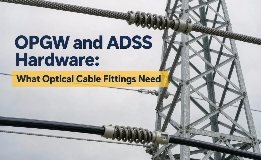
OPGW and ADSS Hardware: What Optical Cable Fittings Need
Optical ground wire (OPGW) and all-dielectric self-supporting cable (ADSS) put fibre on the same poles and towers that carry power conductors. From a distance the hardware looks familiar: suspension points, tension points, dampers, clamps running down the tower. It is tempting for a line crew or a buyer to treat optical cable fittings as a smaller version of conductor fittings and order whatever is on the shelf for aluminium conductor steel reinforced (ACSR) of a similar diameter.
That assumption is where most fibre damage on overhead routes begins. A conductor fitting is designed to hold a metal strand under tension, and if it deforms the conductor slightly, electrical performance is barely affected. An optical cable contains glass fibres inside a buffer tube, and a fitting that crushes, over-grips, or bends the cable too sharply can pass a visual inspection while quietly raising attenuation — or snapping fibres outright the first time the cable moves. This guide walks through what changes when the cable under the fitting is optical, position by position along the route.
OPGW and ADSS: Two Cables, Two Working Conditions
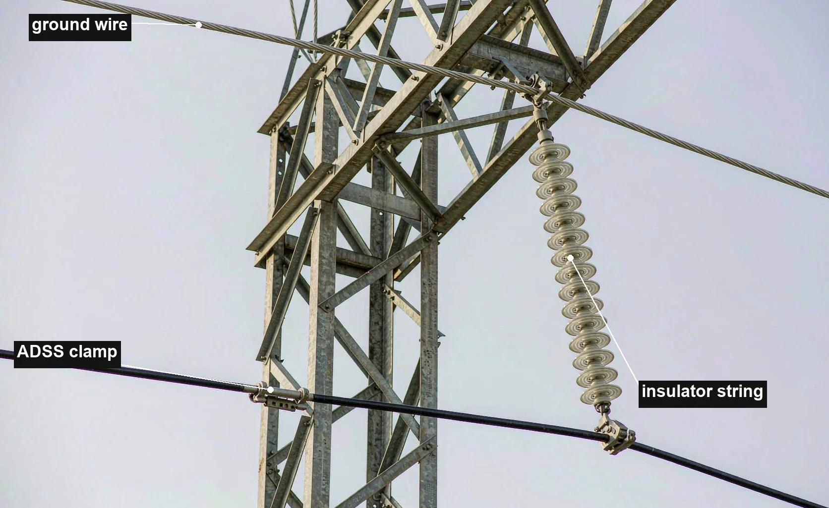
OPGW replaces the traditional shield wire at the top of a transmission tower. It contains a tubular or stranded aluminium armour around one or more stainless-steel or aluminium buffer tubes holding the fibres, so it is a metal cable that happens to carry fibre. Because it sits in the ground-wire position, it forms part of the short-circuit and lightning path: fault current will flow along it to the next tower, so every point where it is clamped, spliced, or terminated must maintain a metallic continuity path capable of carrying that current for the fault duration.
ADSS is the opposite: a fully non-metallic cable with aramid strength members, designed to be installed on existing towers below the conductors while the line stays energised. It carries no fault current and needs no metallic continuity, but it lives inside the electric field around the phase conductors. Dry zones on the jacket can accumulate contamination, and in the strongest field areas the jacket surface can suffer tracking and erosion over time — which is why ADSS route design and hardware placement are tied to the electrical “space potential” at the installation point, not just to mechanical loads.
The distinction matters for every hardware decision that follows. OPGW hardware is metal-to-metal, current-carrying, and sized for fault duties. ADSS hardware is dielectric, isolating, and chosen to avoid stress concentrations in a plastic jacket. A buyer who specifies “tension clamp for 12 mm cable” without saying which cable type can end up with hardware that is wrong in both directions at once.
Why Conductor Fittings Cannot Simply Be Reused
Three mechanical rules separate optical cable hardware from conductor hardware, and each one rules out a whole family of standard conductor fittings.
No crushing, no direct compression on the cable
Bolted and compression dead-ends used on conductors grip by squeezing the strands. On an optical cable, the fibre units sit inside the cross-section, and local pressure deforms the buffer tubes. The resulting bending of the fibres shows up as attenuation that varies with temperature and cable movement. For the same reason, the grooves and inserts in optical suspension and tension hardware are shaped to spread the load over a long contact length rather than concentrate it at two pads. Where rubber or polymer inserts are used, they must match the cable jacket material — a mismatch can either slip or abrade through.
Grip is capped, not maximised
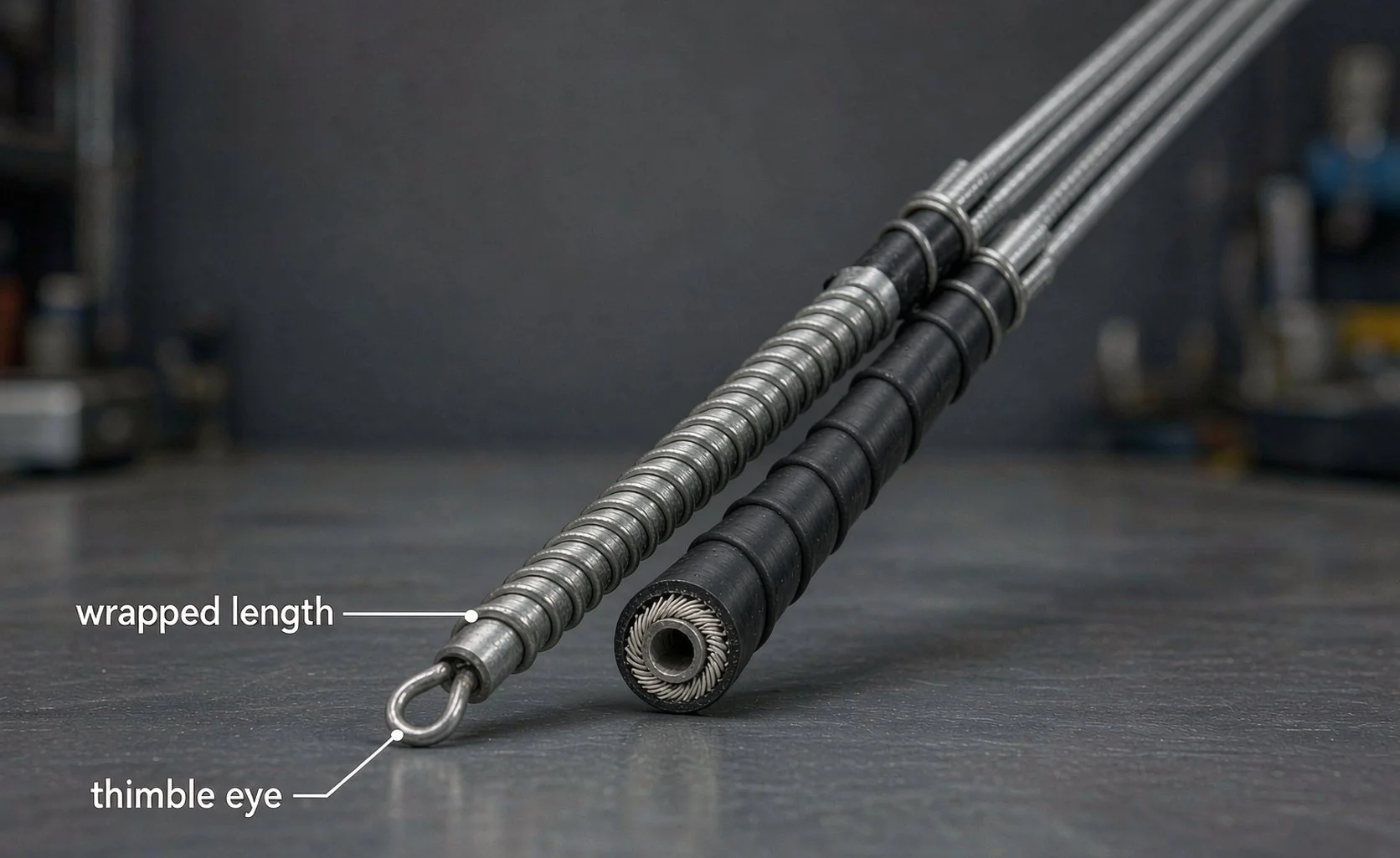
For a conductor, more grip is better up to the strength of the strand. For an optical cable, the rated tensile strength (RTS) is shared between the armour, the strength members, and the tube structure, and the hardware is designed to transfer load gradually. Helical rods — preformed wires wound by hand around the cable, ending in a closed loop or thimble — are the standard solution: each turn takes a fraction of the load, so the hold reaches a specified percentage of RTS without any point of concentrated stress. The consequence is a hard rule: a helical grip is matched to one cable outer diameter and construction, and a rod set specified for a 12.4 mm OPGW will not develop its rated hold on a 12.8 mm cable, nor on a 12.4 mm ADSS with a different lay.
Bending and suspension angle limits are tighter
Fibre tolerates far less bending than a metal strand. Minimum bending diameters for optical cables are many times the cable diameter, and the suspension hardware must respect them at every angle the span can reach — including ice, wind, and everyday thermal movement. For OPGW on long transmission spans this also feeds into the stringing stage: the sheave (pulley) diameter used during pulling must be checked against the cable manufacturer’s limit, because a sheave that is fine for a conductor of the same size can permanently damage fibre units during the pull. The relationship between sag, tension, and when fittings are installed is covered in Sag, Tension and Stringing: Why Fittings Come Last.
None of this makes optical hardware exotic. Tension clamps, suspension clamps, and dampers for conductors follow the same logic of matching load and geometry — see Tension Clamp Types: Compression vs Bolted vs Wedge vs Preformed for how each type grips — but every parameter is re-derived for a cable that must not be squeezed. The table below summarises the practical differences.
| Cable-side requirement | Common conductor practice | What happens if reused on optical cable |
|---|---|---|
| Grip without local pressure on the cross-section | Bolted or compression grip on strands | Buffer tube deformation; attenuation drifts with load and temperature |
| Load transfer over a long wrapped length | Short grip zone, maximum holding force | Stress concentration at the fitting mouth; fibres fail at the first big swing |
| Bending diameter many times cable OD | Tight sheave and throat radii | Micro-bends in fibre; damage often done during stringing, found later |
| Inserts matched to jacket material | Metal-to-metal or generic liner | Slip under cyclic load, or jacket abrasion at the contact line |
| Grip rated as a fraction of RTS, verified per cable type | Grip rated above conductor breaking load | Over-grip: the clamp holds, but the cable fails inside or beside it |
Hardware at Each Position Along an Optical Route
A fibre route on towers is more than spans: it includes anchor points, places where the cable leaves the shield position to descend the tower, joint locations, and spare-cable storage. Each position has its own hardware, its own key parameters, and its own recurring mistakes. Use the table as a checklist when assembling a hardware schedule for an OPGW or ADSS project.
| Position on route | Hardware | Key parameters to specify | Common mistakes |
|---|---|---|---|
| Intermediate support (suspension) | Helical suspension assembly: rods plus a support housing, often with a flexible or rigid hanger | Cable OD and construction; suspension angle range; grip percentage of RTS; armour type for OPGW (metal) vs ADSS (all-dielectric) | Ordering rods by diameter only; exceeding the assembly’s suspension angle; letting the housing rest against tower steel |
| Anchor / angle / dead-end | Helical tension (dead-end) set, possibly paired with a link or clevis matched to the tower fitting | RTS grip rating; cable lay direction; hardware breaking load matched to the mechanical reserve of the cable, not oversized | Reusing conductor dead-ends; installing rods backwards relative to lay; wrong tower-side interface thread |
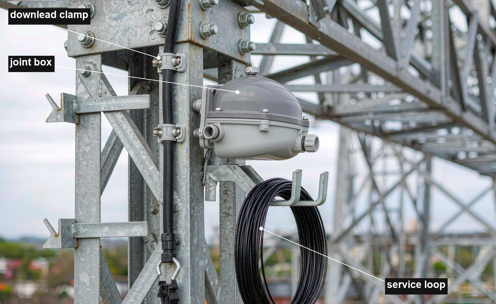
| Downlead along the tower | Downlead clamps at regular vertical spacing | Inner profile to match jacket; spacing per project spec so the cable cannot whip; OPGW downleads may need bonding at defined points | Clamps spaced too widely; metal clamp edges on ADSS jacket; trapping the cable against step bolts |
| Splice location | Joint (splice) box, dome or inline, mounted on the tower or in a ground-level enclosure | Weather rating; OPGW joint must rejoin the armour for fault current; port count for the fibre plan | Generic telecom box used on OPGW with no metallic continuity; box sized without slack loop allowance |
| Slack cable storage | Slack storage bracket (surplus cable rack) holding a coiled service loop | Coil diameter not smaller than the cable’s minimum bending diameter; fixing method that cannot crush the coil | Coil tied too tight; loop stored where maintenance cannot reach it; no loop left at all for future re-splicing |
| Vibration control | Dampers matched to the cable; OPGW on long spans may also need spiral damping wire | Damper tuned frequency band matched to cable mass and tension; installation position per project spec | Assuming fibre cables do not need damping; reusing damper models from the conductor schedule |
| OPGW earthing path | Bonding leads, connectors, and tower attachment at every designated point | Short-circuit current rating and duration per project fault study; contact surfaces protected against corrosion | Bonding installed loosely “to be finished later”; dissimilar metal contacts left unsealed |
Two positions deserve a note on overlap with the rest of a line schedule. Suspension assemblies for ADSS have their own selection logic — the armour rod count, housing size, and angle rating — which is covered in detail in choosing durable suspension clamps for ADSS cable support. And at the very end of the network, where the route leaves the poles and enters a building, fibre drop hardware is a different, lighter product family, covered in the FTTH drop cable clamp guide; the rules in this article apply to the pole-to-tower section, not to the drop segment.
OPGW Specifics: Current-Carrying Hardware
Because OPGW is part of the earth wire system, its fittings are electrical components as well as mechanical ones. Every dead-end, every joint box, and every bonding lead in the fault-current path is sized against the project’s short-circuit study: the fault current magnitude and its duration determine the required cross-section of metallic paths. This is one parameter that must always come from the project specification — never from a supplier’s generic catalogue default — because two lines of the same voltage can have very different fault levels.
Three practical consequences follow. First, an OPGW joint box is not a generic fibre enclosure: it must rejoin the cable’s armour both mechanically and electrically, so its current rating is part of the specification. Second, suspension assemblies for OPGW normally use metallic armour rods and housings, but the assembly still must not crush the buffer tubes, so the rod geometry is cable-specific even though the materials are familiar. Third, the earthing leads from OPGW to the tower body are consumables with a finite life: they flex, corrode at contact faces, and belong on the inspection schedule, not just on the installation drawing — the wider routine is covered in Overhead Line Fittings Inspection.
OPGW also needs vibration protection. A ground wire on a long transmission span is one of the most vibration-exposed cables on the system — wind acts on it for the full span length at lower mechanical damping than the conductors above it. Dampers for OPGW are tuned to the cable’s mass and everyday tension, and their installation positions are usually defined by the project or by the hardware supplier’s span calculations. The mechanism that makes this necessary — vortex shedding, and why damage concentrates at the fitting mouth — is explained in Aeolian Vibration on Overhead Lines: Causes and Control.
ADSS Specifics: Isolating Hardware in an Electric Field
ADSS hardware is chosen to protect a plastic-jacketed cable and to keep the cable out of trouble electrically. The armour rods, tension sets, and suspension housings are all-dielectric or interface with the cable through non-metallic inserts, and there is deliberately no bonding anywhere along the cable. The hardware that touches the tower can be metal; what must never happen is a metallic path through the cable itself.
The field environment drives placement. ADSS installed too close to the conductors sits in a region of high space potential, and jacket degradation in that zone is a slow, contamination-driven process that ends in tracking and erosion. Route design therefore fixes the cable’s attachment height and sag so it stays within the field strength the jacket type is rated for — the cable and hardware schedule inherit that geometry, and a request to “move the ADSS up a bracket to clear a crossing” should trigger a check of the field calculation, not just a mechanical one.
Mechanically, ADSS spans on distribution towers are usually shorter than OPGW spans on transmission towers, but the cable is lighter and the jacket is softer, so the fitting rules bite harder: helical rods must match the exact outer diameter and jacket hardness, downlead clamps must not have sharp metal edges at the jaw, and any tie or clamp used on the slack coil must respect the minimum bending diameter. Where a span crosses an angle, the suspension assembly’s angle rating limits how much deviation it can absorb before a tension set is required instead — the same decision logic as conductor suspension clamps, described in What Is a Suspension Clamp and How to Choose One, but with narrower tolerances.
Installation Sequence and Field Checks
Optical routes are built in a fixed order, and the order is not negotiable: the cable is pulled under controlled tension, sagged to the design curve, only then are the suspension and tension assemblies installed, and finally the downlead, joint box, and slack loop are completed at splice points. Installing clamps before sagging is complete locks in the wrong reference, and it is also the stage where sheave diameter and pulling grips do their damage if they were chosen like conductor stringing gear.
Helical rods are installed by hand, and the details are unforgiving in quiet ways. The cable surface must be clean where the rods wrap; the rod lay direction must match the cable’s outer lay; the wrap must follow the marked start point so the last rods land where the design expects; and no rod can be over-tensioned into a crossed or gapped wrap. A rod set that “looks mostly right” will still transfer load unevenly, and the failure will be reported as a fibre problem months later, not as a hardware problem now.
Verification is where fibre beats copper: the cable can be measured end to end. An optical time-domain reflectometer (OTDR) trace taken before installation, after stringing, and after splice closure gives a numeric record of what each stage did to the cable. Combined with photographs of each completed assembly, this turns any later maintenance argument into a document. The same evidence habit starts earlier, with the receiving checks listed in Incoming Inspection: Checking a Shipment of Line Hardware.
For crews moving from conductor work, the checklist mentality transfers; what changes is which parameter is checked, and against which document. Keep the cable datasheet and the hardware datasheet in the same folder: rod lay, grip percentage, suspension angle, and damper positions all cross-reference between the two, and any number found in neither document should stop the work, not be estimated on site.
Putting the Hardware Schedule Into an RFQ
When ordering, the RFQ for optical cable hardware needs one extra layer compared with conductor fittings: the cable itself must be identified completely, not just by diameter. A workable hardware RFQ states the cable type (OPGW or ADSS), manufacturer and type designation, outer diameter, rated tensile strength, jacket or armour construction, and the span and tension conditions for each position class — plus, for OPGW, the fault-current duty and bonding arrangement from the project study. Quantities should be broken down by position (suspension sets, tension sets, downlead clamps, joint boxes, slack brackets, dampers), because supplier minimum quantities often differ by item.
How to structure a line-hardware RFQ so suppliers can quote without assumptions is covered in How to Specify Overhead Line Fittings in an RFQ, and the same framework applies here with the cable identification block added. Where the project mixes conductor and optical positions, the two schedules should stay separate documents — mixing them is how a conductor dead-end ends up in the OPGW pile.
If your route combines tension points with dead-ending requirements, the interface details worth specifying include the tower-side connection (clevis, eye, or thread) and the mechanical reserve required at each anchor — the selection thinking for tension hardware in general is outlined on our tension clamp and suspension clamp product pages, where optical-cable versions of both assemblies are grouped with their matching rod sets.
Frequently Asked Questions
Can we use standard conductor clamps on ADSS if the diameter matches?
No. Matching diameter is not matching function. Conductor clamps concentrate grip and use metal jaws, both of which a dielectric jacket and the fibre units behind it cannot tolerate. ADSS hardware wraps the load over a long helical length and controls contact pressure through matched inserts, so it must be selected by cable type designation, not by size alone.
Does OPGW hardware really need to carry fault current?
The cable does, and the hardware in the metallic path must follow it. Dead-ends, joint boxes, and bonding leads on OPGW form part of the earth-wire circuit, so their short-circuit current rating for the project’s fault duration is a specification input, taken from the fault study. On ADSS there is no such requirement — the two cable types must never be mixed in one hardware schedule.
Why do helical rod sets have to match the exact cable outer diameter?
The rods develop their hold by the geometry of the wrap: too loose and the set slips, too tight and it over-grips at the mouth. The rated grip percentage of RTS is only valid for the cable construction the set was designed around, which is why suppliers ask for the cable’s type designation rather than just its diameter. A rod set for a different cable of the same size is a different product.
How much slack cable should be left at a splice point?
Enough to re-open the joint for repair without re-stringing, stored in a loop whose diameter respects the cable’s minimum bending diameter, and mounted where a crew can reach it. The exact loop length and fixing arrangement come from the project specification; what matters at the hardware stage is that slack brackets are ordered for every splice location, because a joint without a stored service loop turns a small repair into a new pull.
What should be measured before the route is handed over?
An OTDR trace of every fibre end to end, recorded after the final splice closure, compared against the pre-installation baseline; a walk-down with photographs of every completed assembly; and a check that every OPGW bonding point listed in the schedule exists on the tower. Any attenuation change traced to a fitting position should be fixed before handover, while the crew and the hardware are still on site.
Optical cable fittings ask for a different discipline than conductor fittings: the same route logic, the same position-by-position schedule, but with grip, pressure, and bending re-derived for a cable whose failure mode is silent. Get the cable identification into the specification, keep the two schedules separate, install after sag is final, and verify with light instead of eyes — and the fibre will outlast the steel around it.