



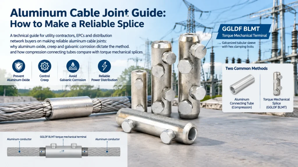
Aluminum Cable Joint Guide: How to Make a Reliable Splice
An aluminum cable joint fails for reasons a copper joint never will. Aluminum reacts with air within minutes to form an oxide layer that is an insulator, it creeps slowly under sustained bolt pressure, and it sits far enough from copper on the galvanic scale to corrode itself at any unprotected interface. Every method that works reliably on aluminum — compression tubes, torque-controlled mechanical splices, bimetallic transitions — is designed around one or more of those three facts. Choose a method that ignores them and the joint will look correct on the day it is made and run hot a year later.
This guide covers what makes aluminum different, the jointing methods that account for it, how to make a compression aluminum cable joint step by step, and the checks that catch a bad one before it becomes a fault.
Why Aluminum Joints Need Their Own Method
The three properties below are not trivia. Each one rules out a technique that is perfectly acceptable on copper.
The oxide film re-forms in minutes
Aluminum oxide is hard, tenacious and non-conductive. It begins forming on a freshly brushed surface almost immediately and reaches a useful thickness long before a crew finishes the joint. This is the reason an aluminum joint cannot rely on simple metal-to-metal contact: the mating surfaces have to be either broken through mechanically, as a compression crimp does, or protected by an oxide inhibitor that keeps air away from the joint face for the life of the installation. It is also why aluminum conductors are wire-brushed immediately before assembly and never left to stand.
Aluminum creeps under bolted pressure
Aluminum deforms slowly under a sustained compressive load — the effect is usually called creep or cold flow. In a bolted connection this shows up as a gradual loss of clamping force: the conductor flattens slightly, the joint relaxes, contact pressure falls and contact resistance rises. Thermal cycling accelerates the process, because aluminum expands and contracts more than the copper or steel it is bolted to. Compression joints sidestep creep by deforming the tube permanently around the conductor. Mechanical joints have to manage it deliberately, with adequate clamping area, spring or Belleville elements in better designs, and a torque check on the maintenance schedule.
Galvanic corrosion at every copper interface
Where aluminum meets copper in the presence of moisture, the two metals form a galvanic cell and the aluminum is the one that corrodes. This is the same problem covered in our comparison of copper and aluminum cable lugs, and it applies just as much to joints as it does to terminations. The accepted answer is the same: never let the two metals touch directly. Use a bimetallic transition connector with a friction-welded copper-aluminum interface, or keep the aluminum joint entirely aluminum and make the copper transition at the equipment terminal instead.
Jointing Methods for Aluminum Conductors
Three families cover almost all aluminum jointing work on distribution networks.
Compression joints with aluminum connecting tubes
A compression joint uses an aluminum tube, often called a connecting tube or splice tube, that slides over both conductor ends and is then compressed by a hydraulic or mechanical crimper. The crimp deforms the tube permanently around the conductor, breaking through the oxide layers on both surfaces and forcing clean metal into contact under enough pressure to create a cold-welded, gas-tight joint. Because the joint is gas-tight, it resists both re-oxidation and moisture ingress — which is why compression is the default for permanent joints, including joints that will be buried or encapsulated.
GGLDF’s GL aluminum connecting tube is used for straight-through splicing of aluminum conductors in distribution networks, and the range includes an oil-seal variant for installations where the joint has to be protected against moisture migration along the conductor. Both types are supplied through the cable connecting tube and terminal range.
Torque-controlled mechanical splice connectors
A mechanical splice does the same job without a crimper. The conductor ends are inserted into a sleeve and clamped by hex bolts tightened to a specified torque. There is no permanent deformation of the sleeve beyond the clamped zones, so the joint can be opened, inspected and re-tightened.
On aluminum specifically, the mechanical method lives or dies on torque discipline. Under-torquing leaves contact pressure too low, the oxide layer is not properly displaced at the contact points, and the joint runs warm. Over-torquing crushes strands and can strip the sleeve thread. Many modern designs use shear-head bolts that snap off at the design torque, which turns a torque wrench requirement into a visual indicator; a plain hex bolt, as used on GGLDF’s BLMT torque mechanical terminal, has to be tightened with a wrench to the value the manufacturer publishes.
Bimetal transition connectors where copper meets aluminum
When a joint genuinely has to move between materials — an aluminum overhead conductor into a copper busbar, for example — the transition should happen inside a connector designed for it, with a friction-welded copper-aluminum barrier, rather than at a bolted face between the two metals. Bimetallic connectors are commonly specified with a tin-plated copper side, since the plating both reduces corrosion and improves contact with the mating surface.
Compression or mechanical: how to choose
| Aspect | Compression joint (aluminum tube) | Torque mechanical splice |
|---|---|---|
| How the joint is formed | Calibrated crimper permanently deforms the tube around the conductor | Hex or shear bolts clamp the conductor inside a sleeve |
| Oxide control | The crimp drives through the oxide across the full barrel; inhibition is factory-applied or applied during assembly | Depends on wire brushing plus inhibitor at installation; bolt pressure displaces oxide only at the contact zones |
| Contact quality | Cold-welded and gas-tight; the standard for permanent joints | Very good when correctly torqued, and directly verifiable |
| Tools required | Hydraulic or battery crimper with matched dies | Torque wrench and hex keys |
| Reversible | No — the joint is permanent | Yes — can be opened, inspected and retightened |
| Maintenance | None after installation | Periodic torque verification recommended where vibration or heavy thermal cycling is expected |
| Typical use | Permanent distribution joints, service joints, encapsulated and buried joints | Field repairs, retrofit work, confined spaces, joints that may need to be reopened |
| Main watch-out | Die and tube size must match; an incomplete crimp is hard to see | Under-torquing is the dominant failure mode; the sleeve must be filled to its rated range |
How to Make a Compression Joint on Aluminum
The sequence below is the general method; where your project specification, the connector manufacturer or the utility standard differs, follow the stricter instruction.
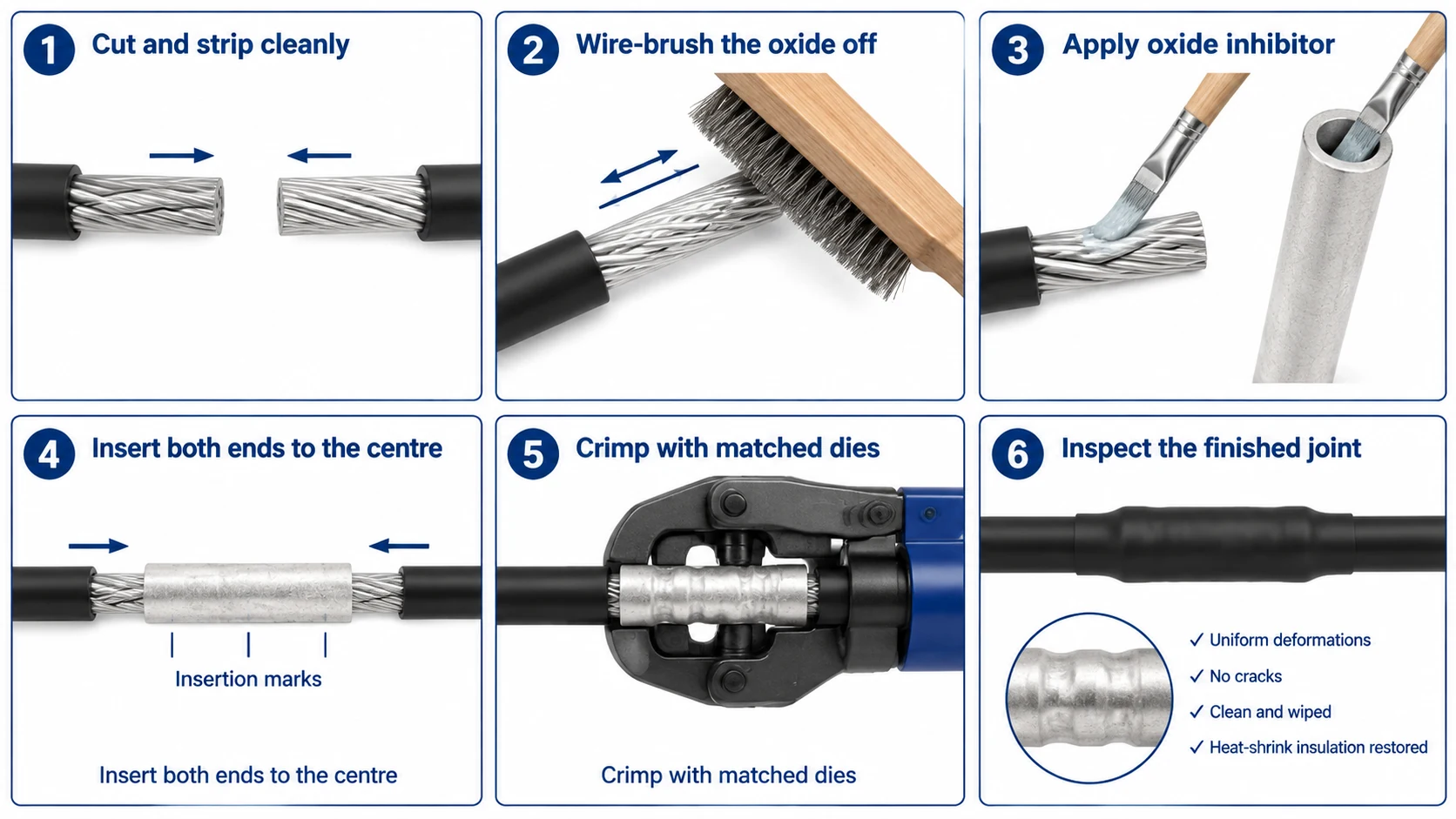
Step-by-step
- Isolate and prove dead. Lock out the circuit, prove it is de-energized, and apply the personal protective equipment your procedures require. Never work an energized conductor to make a joint.
- Cut the conductor cleanly. Use a proper cable cutter and make a square cut. Do not use a hacksaw, and do not allow any strands to be nicked or cut.
- Strip to the right length. The stripped length should clear the tube end by a small margin on each side so the insulation is not trapped inside the joint. Work from the cable manufacturer’s or connector supplier’s dimension rather than estimating.
- Brush the conductor. Wire-brush the conductor until it is bright, and brush the bore of the tube as well. Do not touch the brushed metal with bare hands.
- Apply oxide inhibitor immediately. Coat the brushed conductor and the inside of the tube with the specified joint compound straight away, before the oxide layer has time to re-form. If the metal dulls before you assemble, brush and re-apply.
- Insert both ends to the center. Mark the insertion depth beforehand so both conductors meet at the middle of the tube. They must be fully inserted — a joint where one conductor stops short has far less contact area than the design assumes.
- Select the matching die and crimp. Fit the die that matches the tube size, and complete the full set of crimps in the sequence marked on the tube or specified by the tool manufacturer. Producing fewer, shallower or off-center crimps is the most common way to make a joint that passes a visual check and still runs hot.
- Inspect the crimped joint. Look for uniform deformation along the joint, no cracks in the tube, no bulging of strands outside the tube, and a tube that has not been bent out of line. A widely used acceptance guide limits bend to roughly 2% of tube length, but confirm the figure against your own project specification.
- Wipe off excess compound. Remove surplus inhibitor from the outside of the joint, then restore the insulation and moisture barrier using the jointing kit or heat-shrink system specified for the application. A compression joint is gas-tight; the insulation system protects everything around it.
Checking the Joint After Installation
An aluminum cable joint deserves a measurement, not just a look. Three checks are worth building into the work instruction.
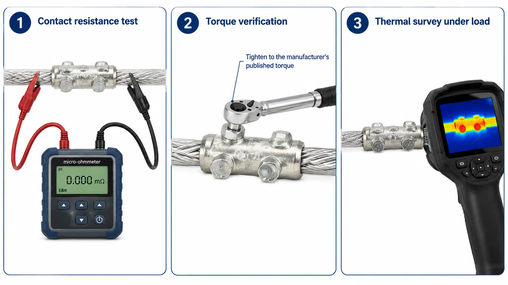
- Contact resistance. Measure across the joint with a micro-ohmmeter or low-resistance ohmmeter and compare the reading against an equal length of the same conductor. A commonly used acceptance guide is that the joint should not exceed about 1.1 times the resistance of the equivalent conductor length — confirm the exact criterion with your project specification.
- Torque verification. On mechanical splices, confirm every bolt has been tightened to the published value and record the figures. Torque is the only evidence that the joint has been assembled correctly, and it is also the check that has to be repeated during maintenance.
- Thermal survey under load. Once the circuit is in service, a thermal imaging survey of the joint under load shows whether contact resistance is producing heat. This is the check that catches a marginal joint that passed the electrical test on a cold day.
Where Aluminum Cable Joints Fail
- Oxide left in place. The conductor was brushed but not inhibited, or was brushed and then left standing before assembly.
- Wrong tube or die. A tube sized for a different conductor cross-section, or a die that does not match the tube, produces a joint with the right appearance and the wrong pressure.
- Not fully inserted. One conductor stops short of the center of the tube, halving the effective contact length.
- Incomplete crimping. Too few crimps, or crimps that are shallow or off the marked positions.
- Under-torqued mechanical bolts. The dominant failure mode of mechanical splices, and the reason torque-controlled designs exist.
- Direct copper-to-aluminum contact. A joint made between the two metals without a bimetallic barrier, in an environment with any moisture present.
- Moisture migration along the conductor. Water entering a stranded aluminum conductor and travelling into the joint — the problem that oil-seal and encapsulated designs address.
- No re-torque in a vibration environment. A mechanical joint on a structure subject to vibration or heavy thermal cycling that is never checked again.
Frequently Asked Questions
Why can’t I just twist two aluminum conductors together?
Twisted joints depend on clean metal-to-metal contact, and aluminum will not hold it. The oxide film re-forms immediately and continues to grow, contact resistance climbs, and the joint heats. Twisted aluminum joints are also mechanically weak and loosen under thermal cycling. Use a compression tube or a mechanical splice.
What is the difference between a connecting tube and a cable lug?
A connecting tube makes an inline joint between two conductor ends — the joint sits in the middle of the run. A cable lug terminates one conductor end at a piece of equipment, so the connection is made through a bolted palm. Both are covered by the same family of standards, but they solve different problems; the crimping process itself is described in our cable lug crimping guide.
Can a compression joint be reused?
No. The crimp permanently deforms the tube, so the joint has to be cut out and remade. If the installation is one you expect to reopen — for testing, reconfiguration or temporary supply — use a torque mechanical splice instead.
Is a mechanical splice as good as a compression joint?
When it is correctly torqued, a modern mechanical splice achieves a stable, low-resistance connection on aluminum, and it can be verified and re-tightened in service, which a crimp cannot. Compression retains the advantage in permanent, high-current and encapsulated installations because the joint is cold-welded and gas-tight. The right answer usually depends on whether the joint will ever need to come apart.
Which standard applies to aluminum cable joints?
Connectors of this type are commonly specified against IEC 61238-1 for compression and mechanical connectors on power cables, and against ANSI C119.4 for connectors used between aluminum-to-aluminum or aluminum-to-copper conductors. Project specifications often add local utility requirements. What matters when you are buying is that the test evidence names the connector and the conductor combination you are actually installing, not just the product family.
Do aluminum joints need maintenance?
Compression joints do not. Mechanical joints do: the accepted practice is to re-check the bolt torque on a defined cycle, and more frequently where the joint is exposed to vibration or large temperature swings, because thermal cycling and creep both act to relax the clamping force over time.
Specifying Aluminum Joints and Connectors
An aluminum cable joint is one of the few places in electrical work where a small specification error turns into a hot joint rather than an obvious failure, so the useful conversation with a supplier is about conductor data rather than unit price. Send the conductor material, cross-section and class, the joint type you intend to use, the environment the joint will sit in, and whether the joint will ever need to be reopened.
GGLDF manufactures aluminum connecting tubes, bimetal transition connectors and torque mechanical terminals for distribution networks, alongside the copper tubes and terminals used on the copper side of the same projects. Tell our team what you are jointing and where, and we will confirm the matching connector and the tooling it needs — get in touch with our technical sales team.