
How to Install a Tension Clamp: Compression, Bolted, Wedge
A dead-end tension clamp transfers the full working tension of a conductor span into a pole, tower or termination structure. Unlike a support fitting, it must do that without slipping along the conductor, crushing the strand, or creating a resistance problem at the interface. For the crew and the inspector, the clamp is either correctly seated and secured, or the span is not safe to energise.
This guide is for installers, foremen and site inspectors. It covers the four structural families found in the field — compression, bolted, wedge and preformed — then the checks common to all of them. It does not compare designs; if you are still selecting, start with the comparison of tension clamp types. Once the drawing fixes the type, the job is execution.
Before You Start: Drawings, Ratings and Site Checks
Confirm the clamp model against the drawing before unpacking: conductor designation, outside diameter, stranding and material must match what the clamp was specified for, and the rated holding strength must exceed the stringing tension in the drawings. Never substitute a near-enough size or mix components from two assemblies. Inspect the hardware for casting defects, cracks, damaged coating and crossed threads, and reject anything dropped on a hard surface. Then confirm the structure can take the load — bracing, guys, crossarm and attachment point.
Lay out and check the tooling first: hydraulic press with the correct die set, calibrated torque wrench, come-along and pulling grips, conductor brush, inhibitor compound, binding wire, and the supplied split pins and retainers. Confirm the wrench is in calibration and the press completes a full cycle. Set the exclusion zone and apply the earthing and fall protection the site rules require.
Conductor End Preparation and Binding
Cut the conductor square with an approved cutter and deburr the end. Bring splayed strands back into lay by hand; do not hammer the end straight. Wire-brush the aluminium strands bright, working along the lay, and clean the steel core separately on ACSR. Oxide is insulating and quick to reform, so apply the specified inhibitor compound immediately after brushing. The same preparation applies to every mechanical connection on the line; see our aluminum cable joint guide.
Leave the tail the length the drawing specifies, clear of the structure, adjacent phases and stays. Bind the tail before final cutting so the lay cannot unlay, and fit armour rods or a mouth binding now.
Compression Tension Clamp: Hydraulic Crimping
A compression dead-end is joined to the conductor by plastic deformation, pressing barrel and strand into one mass. There is no bolt to re-tighten and no wedge to re-seat, so a defective crimp is permanent. The checks have to happen at the moment of pressing.
Choose the Right Die, Then Verify It
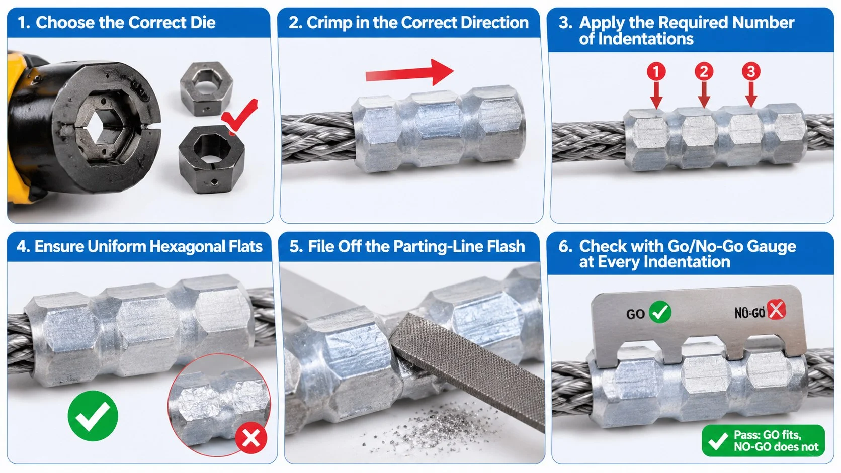
The die set is identified by clamp model and conductor size in that model’s specification sheet. Never choose by eye or leave the previous size in the press: check the die marking against the clamp packaging and the sheet before the first press, and inspect the faces for chipped edges, packed-in aluminium and rust. A worn or wrong die gives a crimp that measures correctly at the flats but never develops the designed grip. The same die discipline is described in our cable lug crimping guide.
Crimping Sequence and Number of Indentations
Direction of travel, spacing, overlap between adjacent indents and total count all come from the clamp’s installation instruction and the drawings; follow them as written. Working from the anchor end toward the tail is common but not universal, and some designs require the opposite. Do not add indents beyond the specified count: over-crimping extrudes metal, distorts the barrel and can displace the steel core on ACSR. Take each press to full compression, holding and releasing per the press manufacturer’s procedure, because a partial stroke leaves a step the gauge will reject.
Post-Crimp Appearance and Gauge Check
Read the finished crimp before moving on: uniform flats with no twist, die halves meeting cleanly at the parting line, no cracks, no strand where it should be enclosed, no core displacement, and the tail protruding by the specified amount. Then gauge it. The go/no-go gauge specified for that clamp and die combination must pass on the go side and not pass on the no-go side, checked across the flats at every indent — the only measurement that confirms compression actually happened.
Flash and Burr Treatment
The fin of metal squeezed out along the die parting line is normal but must be removed. File it off working along the barrel without cutting into the wall or the conductor, and round any sharp edge at the clamp mouth. Clean off excess inhibitor and seal the exposed conductor end as the drawing requires.
Bolted Tension Clamp
Bolted dead-ends are common on LV ABC and distribution terminations where a hydraulic press is impractical. They hold the conductor purely through bolt-generated clamping force, so the whole job is developing that force evenly and keeping it — slip, strand damage and heating all trace back to uneven bolt load.
Seat the Clamp Before You Tighten
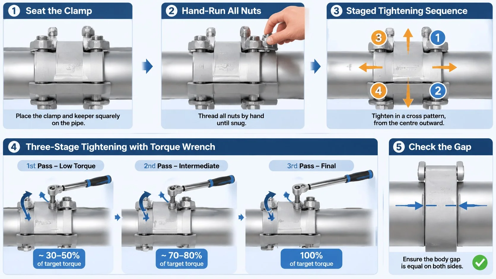
Position the body so the conductor lies in the full length of the groove, not just the middle, and the keeper seats squarely with no gap at either end. Hand-run every nut so the assembly closes finger-tight and captures the conductor. Never take one bolt to final torque while the others are loose: the body cocks over and the clamp slips regardless.
Tightening Sequence
Use the sequence in the model’s instruction sheet. Where none is published, use a staged cross or star pattern from the centre outward. Work in stages rather than one pass: a first pass to a low fraction of the final value, a second higher, then the final pass. The visual cue is that the gap stays equal on both sides after every pass. Check it again after tensioning — a gap opening on one side means the clamp was not seated square.
Torque Values and Where They Come From
Use the value in that clamp model’s specification sheet, confirmed against the drawings. Do not borrow a figure from another size, another manufacturer or another crew’s habit: the correct value depends on bolt diameter, grade and thread condition. Use a calibrated torque wrench for the final pass; an impact driver is fine for running nuts up but is not a measurement. Do not lubricate threads unless the instruction says to: it changes the torque-to-tension relationship and the same figure can shear the bolt. With shear-head bolts, tighten until the head shears at the designed point and stop.
Re-Tightening
Re-torque is not optional on this clamp type. Aluminium creeps under sustained load, coatings settle, and vibration does the rest. Check torque again after the conductor has been tensioned and settled, and again at the interval the maintenance documents specify, recording date and structure each time. If a bolt will not hold its value across two checks, investigate: recurring preload loss means a worn thread or the wrong clamp size.
Wedge Tension Clamp
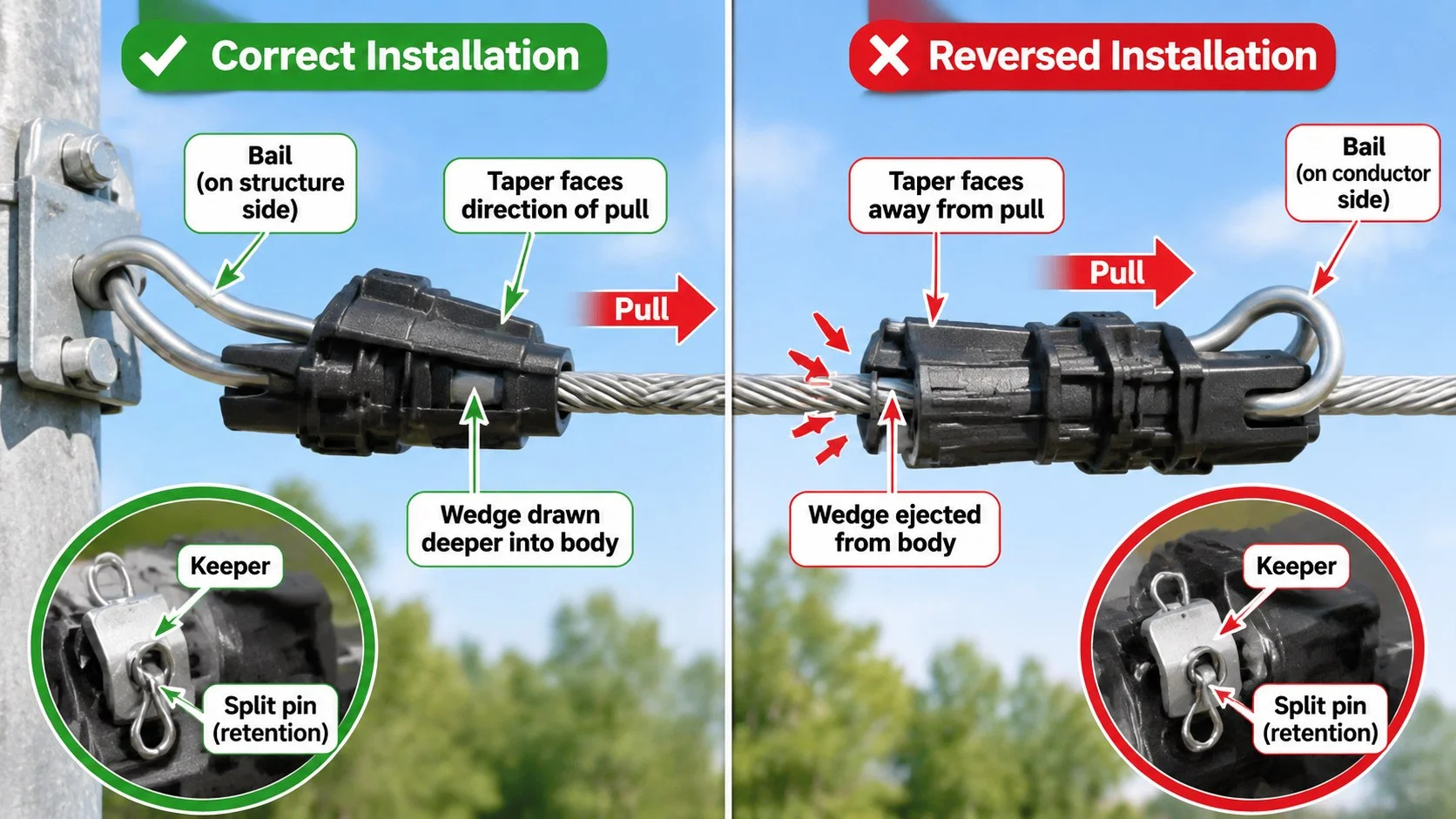
A wedge clamp is self-energising: conductor tension pulls the wedge deeper into the tapered body, so grip rises with load. That only works if the wedge starts in the right place and points the right way. Get either wrong and the geometry works against the span.
Wedge Seating and Conductor Pre-Tension
Pass the conductor through the body into its groove, place the wedge over it and start it into the taper by hand, then tap it home with a soft-faced tool. Never strike a coated surface with a steel hammer: the deformation is permanent. Apply pre-tension with a come-along to the value in the drawings, enough to seat the wedge rather than to full design tension while other parts are still being verified. Under full tension the wedge should draw slightly further in; if it has moved outward, detension and start again.
Wedge Body Direction
The taper must face the direction of pull, so that tension draws the wedge into the body rather than out of it. This is the most dangerous error with this type, because an inverted assembly can hold long enough for the crew to leave, then release under load. Before loading, confirm the load or line marking points toward the span and the bail or clevis is on the structure side, then check again from where you can see both the marking and the taper.
Anti-Loosening and Retention
Fit the keeper, cotter or clip supplied with the assembly, together with its split pin: that is what stops the wedge backing out through load cycles and vibration. Where a locking tab or deformable clip is used, form it exactly as the instruction shows. Confirm the seating once more after the jumper and bonding are fitted.
Preformed (Helical) Tension Clamp
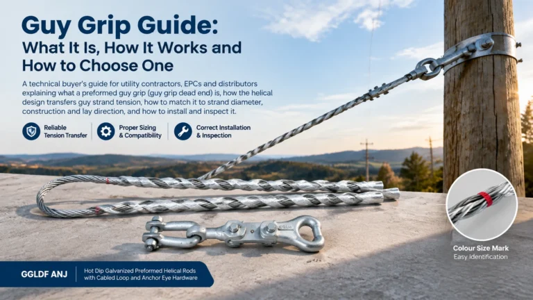
Preformed helical dead-ends grip by friction distributed along a long wrap, with no bolts and no dies. The result depends on the rods being wrapped correctly; once they are on, the grip cannot be inspected. The same family is used for guy terminations, covered in our guy grip guide.
Wrapping Direction
The lay of the rods must match the lay of the conductor — a right-hand lay conductor takes a right-hand lay set. A reversed set will not develop grip. Confirm it three ways: the colour code or identification marking, the start mark, and the field check of laying a rod alongside the conductor. If any two disagree, resolve it before wrapping. Start at the marked point and wrap in the direction shown, keeping the rods snug and parallel with no gaps, crossovers or twist, and use the recommended tool rather than levering with pliers, which scores the rods.
Single Use, Never Reused
Preformed dead-ends are single-use items. Once applied and loaded, the rods have taken a permanent set and the grip is gone. Do not remove and re-apply a set, do not reuse one stripped from a de-energised span, and do not mix parts of one set into another. Where the drawing treats the thimble as part of the assembly, replace the whole termination.
Finish and Check
Complete the wrap fully — a half-applied set is worse than none, because it looks finished from the ground. Clip or tape the ends as the instruction requires, with the legs seated in the loop. After tensioning, the rods should lie evenly spaced and flat, with no gap opened and no sign the set has walked. Any of those symptoms means replacement, not repair.
Bonding, Grounding and Jumpers
Electrical continuity is a separate job from mechanical anchoring, and confusing the two causes most thermal problems at dead-ends. Make the bond or earth connection to the structure’s designated earthing point, never to the clamp body: current routed through the mechanical interface holding the span turns any resistance there into a heater. Prepare the contact as you prepared the conductor: bright metal, inhibitor where specified, tightened to the specification sheet. Where the design uses a piercing connector for a bonding or tap-off connection, follow its sequence and torque; see our insulation piercing connector material.
Jumpers across a tensioning section need enough slack that they never carry mechanical load or bear on the clamp or insulator. A jumper pulled tight looks tidy on installation day and then fatigues at the terminal. Check jumper clearance across the full range of sag the design allows.
Anti-Loosening Hardware and Split Pins
Retaining components are easy to lose and easy to substitute badly, and they are the last defence against a loaded assembly working loose. Use the split pin of the specified diameter and length, pass it fully through, and bend the legs as the drawing shows — one over the end of the pin, the other back along the body. A pin left straight falls out; one flush-cut to length has nothing to retain it.
Never reuse a split pin once bent, and never substitute a nail, a piece of wire or a bolt of another grade. Use spring washers, lock nuts or thread-locking compound only where the assembly specifies them. The pin connecting the bail to the insulator or structure needs full engagement, with the cotter through the castellated nut rather than resting against it. Apply anti-seize or thread treatment to the specified parts only.
Post-Installation Inspection Checklist
Work through this after installation and again after the span is tensioned, and treat any failure as a stop-work item rather than a note for later.
| Item | What to check | Acceptance | If it fails |
|---|---|---|---|
| Clamp identification | Model and marking against the drawing | Matches the specified model and size | Replace; no substitution |
| Conductor match | Type, OD and stranding against the clamp marking | Identical to the drawing | Stop and resolve before loading |
| Crimp count and spacing | Number of indents, direction, overlap | As the instruction and drawings specify | Cut off and re-terminate |
| Go/no-go gauge | Gauge at every indent, across the flats | Go passes, no-go does not pass | Reject the crimp |
| Crimp appearance | Uniform flats, no twist, cracks or core displacement | Clean and uniform; tail protruding as specified | Reject and re-terminate |
| Flash removal | Parting-line fin and sharp edges | Trimmed flush; barrel intact | File and re-inspect |
| Bolt torque | Final torque against the specification sheet | Measured with a calibrated wrench | Re-torque; investigate if it will not hold |
| Body gap | Gap between body and keeper, both sides | Equal after every pass and after tensioning | Release, re-seat, re-tighten in stages |
| Wedge direction | Load marking and taper against the pull direction | Tension draws the wedge into the body | Detension and re-install correctly |
| Wedge seating | Movement under full tension; tail protrusion | Drawn in; protrusion within range | Re-seat; reject if it backs out |
| Lay direction | Rod lay against conductor lay; colour code; start mark | Lay matches; all checks agree | Remove and fit the correct set |
| Rod application | Parallel rods, no crossovers or gaps, ends flat | Even, snug wrap over the full length | Replace the set; single use only |
| Single-use items | Preformed sets, split pins, shear-head bolts | New; not reused or substituted | Replace all of them |
| Split pins and retainers | Correct size, fully through, legs bent as drawn | Fitted and formed; no substitutes | Fit the correct pin |
| Bonding and earthing | Connection to the designated earth point | Clean, inhibited, tightened to the specification sheet | Re-prepare and re-make the connection |
| Jumper | Slack, clearance, contact with clamp or insulator | Carries no mechanical load | Re-form or re-length the jumper |
| Conductor tail | Length and binding | Within the drawing; bound; clear of phases | Cut back and re-bind |
| Protection and records | Inhibitor, end sealing, coating repair, logs | Applied as specified and recorded | Complete and sign off before energising |
Common Installation Mistakes and Their Consequences
These defects recur in field audits and failure investigations.
| Mistake | Why it happens | Consequence | Correct practice |
|---|---|---|---|
| Wrong die or die size | Chosen by eye, or left in the press | Crimp measures correctly but never grips; conductor pull-out | Verify the die marking against the specification sheet; gauge every crimp |
| Extra indentations “for safety” | Presses added beyond the specified count | Barrel distortion, core displacement, residual stress | Use the number of indents the drawing specifies |
| One bolt fully tightened before the others | Sequence rushed on a multi-bolt body | Body cocks over; uneven clamping force; slip | Staged cross pattern from the centre outward |
| Torque taken from memory | No specification sheet on site | Under-clamped and slipping, or sheared bolts | Use the value for that model with a calibrated wrench |
| Re-torque skipped | Assumed unnecessary once the clamp looks tight | Creep and vibration loosen the assembly; interface heating | Re-torque after tensioning and at the specified interval; log it |
| Wedge facing away from the pull | Taper not checked against the span direction | Tension drives the wedge out; the span releases | Verify the load marking and taper before loading |
| Rods wrapped against the conductor lay | Lay not confirmed, or mixed sets on site | No grip; the assembly pulls off under tension | Check colour code, start mark and lay against the conductor |
| Reusing a preformed set or a split pin | Salvaged from a previous attempt | Work-hardened rods, no retention, assembly releases | Single use only; replace the whole assembly |
| Clamp body used as the earthing point | Convenience; the clamp is nearest | Current through the mechanical interface; arcing | Bond to the structure’s designated earthing point |
| Jumper pulled tight | Formed to look tidy rather than with slack | Jumper carries load and fatigues at the terminal | Form the loop with slack; check clearance at all sags |
| Oxide not removed, inhibitor omitted | Brushing skipped under time pressure | High-resistance interface; joint degradation | Brush to bright metal and apply the specified inhibitor |
| No gauge check and no record | Appearance trusted instead of measurement | Defective crimp passes unnoticed; latent failure | Gauge every crimp; record die ID, operator and structure |
Frequently Asked Questions
How do I know which die to use for a compression tension clamp?
Take it from the specification sheet for that clamp model and conductor size, then confirm it three ways: the marking on the die, the marking on the clamp packaging, and the sheet itself. If the three do not agree, resolve it before pressing — a crimp made with the wrong die passes a visual check and still fails to hold.
Can I use an impact wrench to tighten a bolted tension clamp?
An impact driver is acceptable for running nuts up, but not for the final torque: it does not deliver a measured bolt load, and the gap between slightly loose and correctly clamped is exactly the band it cannot resolve. Use a calibrated torque wrench in the staged sequence for the final pass, and record the value.
Do I need to re-torque a bolted tension clamp after tensioning?
Yes. Aluminium creeps under sustained load, coatings settle, and vibration completes the process. The first re-torque, after the conductor has been tensioned and settled, recovers most of the preload lost in that settling. Re-torque again at the interval the maintenance documents specify, logging date and structure each time.
Can a preformed dead-end be removed and reused?
No. The rods take a permanent set as soon as they are applied and loaded, and the grip comes from that first application. Remove it, discard it, and install a new set. Where the drawing treats the thimble as part of the assembly, replace the whole termination.
What is the quickest way to confirm a wedge clamp is the right way round?
Check that the taper narrows in the direction the conductor is pulling from, so tension draws the wedge deeper into the body rather than ejecting it. Then confirm the load or line marking points toward the span and the bail or clevis is on the structure side. Make both checks before loading, and confirm the wedge has drawn inward under full tension.
Final Word for the Crew
Every type here performs as designed, and each fails in a characteristic way when one step is skipped. The pattern across all four families is the same: the result depends on details you can only verify during installation. Check the die, follow the sequence, use the value in the specification sheet, confirm the direction before loading, gauge the crimp, and write it down. The product pages for our tension clamp range carry the model identification and specification references these checks depend on, and our suspension clamp selection article covers the adjacent support fittings in the same span.