Insulation Piercing Connector Installation: Torque, Shear Nuts and Sealing
Insulation piercing connector installation comes down to three things: seat both conductors fully in their channels, tighten the shear-head nut until the hex head snaps off at its calibrated torque, and confirm the seal and end cap are seated before you leave the pole. None of it should be done by feel. The torque is built into the nut and the conductor range is set by the model — get either wrong and you have a joint that looks finished on the day and turns into a hot spot months later.
What follows covers the installation itself: positioning the cables, what the shear nut does, why you stop turning it, how to handle the grease and end cap, what to check afterwards, and the mistakes behind most failed tap-offs. New to the fitting? Start with what an insulation piercing connector is.
Tools and Checks Before You Start
Most IPC failures are decided before anyone puts a spanner on the nut: wrong model for the cable, wrong socket, or a connector that has been rattling around a bag with grit in the grease.
Match both conductors to the rated range
Every IPC carries two ranges — one for the main (run) conductor, one for the branch (tap) conductor. Both cables have to fall inside them. Read the ranges off the connector body or the datasheet; do not infer them from the channel size or from what a similar connector was used for last week.
The insulation counts as much as the conductor. Teeth are set to penetrate a certain insulation thickness and material, and conductors that are thicker-insulated, sheathed, or double-insulated stop the halves closing evenly, defeating the teeth and the seal together. That is one reason IPCs rated for aerial bundled cable are not automatically acceptable on PVC consumer tails — check where IPCs should and should not be used before fitting one inside a property.
The tools that matter
- Correct socket or spanner size. A loose socket rounds the nut and can damage the shear neck before any real torque is applied.
- Something to hold the body. Rotational force travels down both conductors into whatever they terminate in, and a meter or board termination is not built to absorb it.
- Insulated tools and PPE rated for the voltage if you are working live or near live parts.
- Not an impact driver. Impact delivers torque in shocks, which can break the head before the teeth have fully set.
- A torque wrench only if the sheet asks for one — usually for a separate bolt, not the shear nut.
| Check | What to look for | Why it matters |
|---|---|---|
| Conductor sizes | Both main and branch inside the ranges marked for the model | Teeth cannot reach the strands and the seal cannot close |
| Insulation type | Matches what the connector was designed and tested for | Thicker or sheathed insulation prevents the halves meeting evenly |
| Material variant | Suits aluminium-to-aluminium, copper-to-copper, or the bimetallic case | Mixed metals without the right plating corrode at the contact |
| Connector condition | Body uncracked, grease clean, shear neck not already deformed | A damaged or used connector will not deliver its torque |
| Cable at the piercing point | Insulation intact, no cuts or crushed section | Damaged insulation gives unpredictable contact and no seal |
How to Position the Main and Branch Conductors
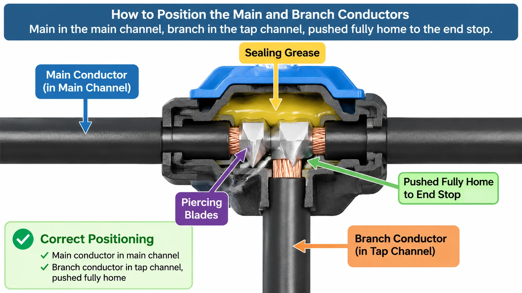
Main conductor in the main channel, branch conductor in the tap channel. On most designs the channels differ in size and the body only lets the cables seat one way round; if you have to force a cable in, you have the wrong model. Equal-size connectors have matching channels, but the ranges still apply. See how the piercing principle and connector types differ if you are unsure which design you have.
The branch conductor must go all the way home, to the end stop at the cap end. Cut it square and leave no splayed strands outside the body. A half-seated branch is the usual cause of a joint that shears correctly and still fails, because the teeth bite the end of the cable instead of its full contact length.
Three things not to do:
- Do not strip the insulation. The connector pierces it and seals around the pierced point.
- Do not scrape or thin it to help the teeth. You change the depth they must cover and remove the material the seal presses on.
- Do not pre-pierce, nick, or drill the cable. Damage outside the body is a track for water.
Wipe surface dirt and moisture off the cable where it will sit in the body. Keep both cables straight through the connector with no twist or kink where they leave it, and support them so the connector is not carrying the weight of the branch or the span. Never install a replacement at the point where a previous IPC was removed — that insulation has already been pierced. Move along the cable.
Insulation Piercing Connector Installation: The Step-by-Step Sequence
The order below is the general pattern. Where the instruction sheet for your model differs — cap before or after tightening, one nut or two, a stated sequence — the sheet wins.
- Confirm the sizes and take the connector out of its bag only when ready.
- Set it to the installation position. Most arrive with the nut backed off; do not dismantle it.
- Lay the main conductor in and let it sit naturally, without pushing it into a curve.
- Lay the branch conductor in and push it fully home to the end stop.
- Close the halves by hand. If one side stands proud, something is trapped or a cable is out of range — find out what first.
- Start the nut by hand to avoid cross-threading. A cross-threaded shear nut never delivers its torque.
- Hold the body steady and tighten with a slow, even pull. At least one utility network standard specifies roughly a minute per bolt, so the head shears at the load it was calibrated for.
- On two-nut designs, follow the stated order. Shearing the main side and leaving the branch side part-tightened gives you a half-finished joint.
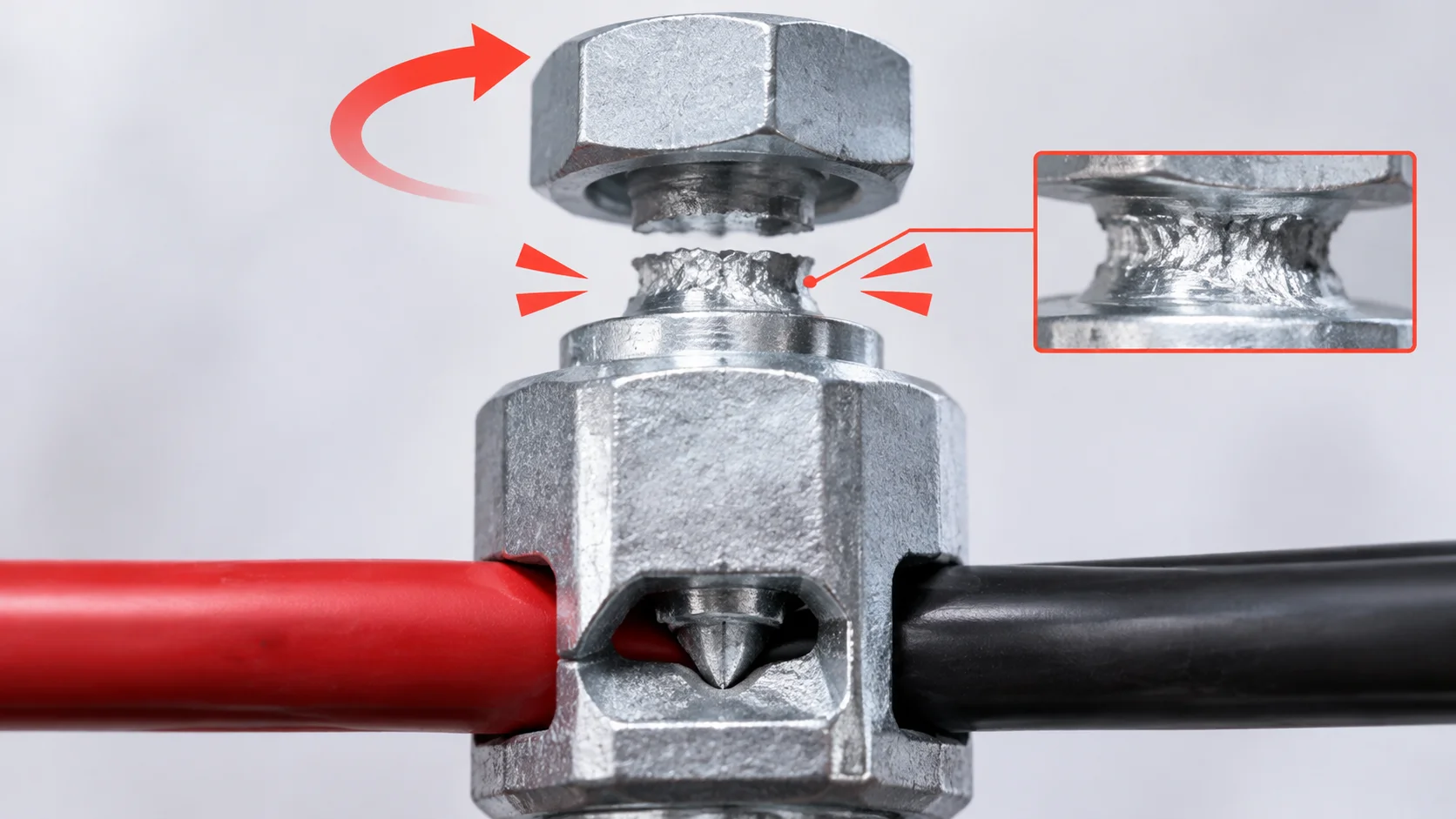
- Keep going until the hex head shears off , and catch the broken piece.
- Fit the end cap fully over the branch cut end if it is not a captive design.
- Check the result — visual check and pull check, as below.
What the Shear-Head Nut Does and Why You Stop Turning It
A shear-head nut is two pieces of metal joined by a neck machined to fail at a specific torque. Below that torque it behaves like an ordinary nut; at that torque the neck breaks and the driving hex head comes away in your socket, leaving a short smooth stub.
It exists because “tight enough” cannot be judged by hand. How much force an installer puts on a spanner depends on the tool, the gloves, the working position and temperature. The shear neck removes that variable: the connector decides when it is tight, not the person holding the wrench. It also sets a ceiling, because the torque that makes teeth pierce insulation and press on strands is close to the torque that deforms the strands or cracks the body.
Once the head is off, the tightening is finished. Three things follow:
- Do not turn the stub. Gripping it with pliers applies unmeasured torque to strands and a seal already set once.
- Do not substitute a standard bolt and nut. You lose torque control and cannot tell whether the joint is under- or over-tightened.
- A sheared head is not proof on its own. It proves the nut reached its torque, not that the cables were in range, seated, or sealed.
An IPC is a single-use fitting. The teeth deform as they pierce, the seal compresses once, and the shear nut spends itself. A connector that has been installed and removed goes in the bin.
Torque Control in Insulation Piercing Connector Installation
There is no universal torque figure for IPC installation, and any single number presented as applying across the category is wrong. The value belongs to the model: it is set by the teeth, the insulation thickness the connector is designed to pierce, the conductor material, and how far the seal must compress. On a two-nut design the main-side and branch-side nuts may not share a value.
Get the figure from the datasheet, the marking on the body, or the packaging. If a supplier cannot state the shear-off torque for a model, settle that before the connectors go up a pole.
The torque controls three things at once: penetration depth, contact force between teeth and strands, and seal compression. That explains both failure modes.
- Too little torque. The teeth fail to reach the strands or touch them with too little force. Contact resistance rises, the joint heats under load, heat accelerates oxidation, resistance climbs further — and an under-tightened IPC melts its own body or burns the conductor.
- Too much torque. Strands are flattened or partly cut, the body can crack, and the seal can be squeezed out of position. A cracked body or extruded seal is a water path to a pierced contact.
Temperature plays a part too. Insulation is stiffer cold, and a connector tightened onto very cold or ice-coated cable is not being installed in the condition it was tested in. Follow any minimum installation temperature the manufacturer states.
| What you see | Likely cause | What to do |
|---|---|---|
| Joint hot under load | Under-torque, wrong size, or branch not seated | Fit a new connector at a different point on the main cable. Never re-tighten. |
| Head shears with no resistance | Conductor out of range, nut damaged beforehand, or impact driver used | Replace it and re-check both sizes. |
| Nut turns, head never shears | Cross-threaded, wrong model, or halves cannot close | Stop. Do not force it. Remove and start again. |
| Body cracked or seal squeezed out | Over-torque, or oversize conductor preventing even closing | Replace and check the conductor range first. |
| Water or corrosion inside | End cap missing or half-fitted, or undersize conductor | Replace, fit the cap fully, confirm both sizes. |
Sealing, End Caps and Waterproof Grease
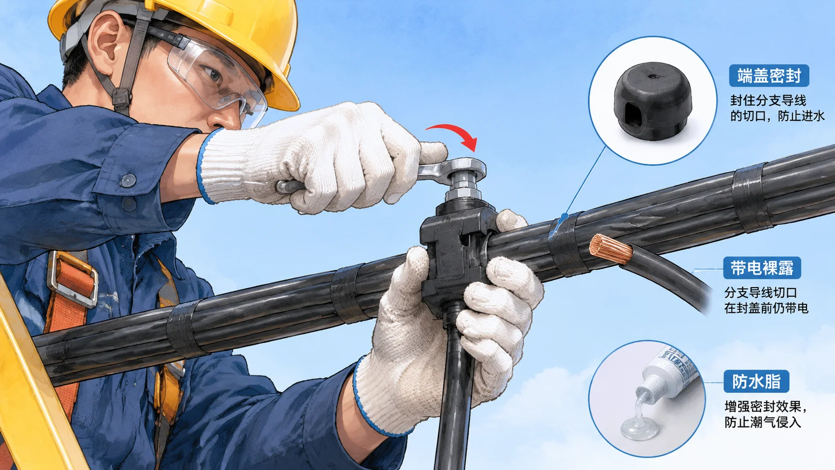
The grease inside the body and around the teeth is part of the design, not packing residue. It excludes air and moisture from the pierced contact so the conductor does not oxidise after the teeth break through. Do not wipe it out, do not clean the inside with solvent, keep the connector bagged until you fit it, and do not top it up with a different grease unless the manufacturer names one.
The end cap seals the cut end of the branch conductor, which is live and exposed until capped. On a captive design, slide it fully on until it bottoms out; on a separate-cap design, push it all the way. A cap pushed on halfway is off within a season. Whether it goes on before or after tightening depends on the model — check the sheet.
Sealing depends on the same thing the electrical contact depends on: correct conductor size. Undersize leaves a gap the seal cannot close; oversize stops the halves meeting squarely. Where the design and local practice allow it, orient the connector and form a drip loop in the branch so water does not run into the body. Use an approved mastic or heat-shrink where your utility specifies one, but do not wrap a joint you are unsure about in tape — you hide the evidence and can trap water against the body.
What to Check After the Nut Has Sheared
- Clean shear at the neck. A partial, jagged, or bent break means the tightening went wrong.
- Halves seated evenly , no gap, no cable insulation pinched between them.
- No crack in the body , including around the channels and the nut.
- Branch fully home and capped , no strands visible outside the body.
- Pull check — a firm tug on the branch conductor. Anything that moves is a failed joint, not one to tighten again.
If any of those fail, the connector comes off and a new one goes on at a different point on the main cable. Check again later as well: a thermal scan under load during the first weeks catches the high-resistance joints that looked perfect on installation day. Scan while the circuit is carrying current — an unloaded joint can read cool and still be faulty. What the body material does once a joint genuinely overheats is a separate question, covered in the glow wire test for IPC connectors.
Installation Mistakes That Show Up as Hot Joints
- Wrong cross-section. Both conductors, in range, checked against the marking.
- Only one side tightened on a two-nut design.
- Turning the stub after the head shears.
- Reusing a removed connector — teeth deformed, seal compressed, nut spent.
- Impact driver or fast ratcheting.
- A replacement at the same point on the main cable.
- Letting the connector carry mechanical load. It makes the electrical connection, not the strain relief.
- Missing or half-fitted end cap — live end exposed, water path into the body.
- Installing outside the connector’s scope : sheathed, double-insulated, or indoor consumer tails.
- Fitting the wrong material variant — aluminium-to-copper needs the bimetallic version.
When an IPC Is Not the Right Fitting
Joining bare conductor to bare conductor is a parallel groove clamp job. A PG clamp can be inspected, loosened, and re-tightened — a different maintenance proposition from a sealed single-use IPC.
Mechanical load is not a connector job either. An IPC holds the electrical contact; drop hardware holds the cable. For a customer drop, the drop cable clamp guide covers that side of the work.
Insulation Piercing Connector Installation FAQs
Do you need a torque wrench to install an IPC?
Usually not. The shear-head nut is the torque control; its purpose is to remove the need to measure torque on site. Use a wrench where the manufacturer gives a value, typically for a separate bolt. Otherwise concentrate on the right socket, steady tightening, and stopping when the head shears.
Can you re-tighten an IPC after the head shears off?
No. Once the head is gone there is no calibrated geometry left, and turning the stub applies unmeasured force to strands and a seal already set once. A joint that seems to need re-tightening needs replacing.
Can an insulation piercing connector be reused?
No. Fit a new one, at a different point on the main cable rather than where the old one sat.
What torque should I use?
The one published for that model. No figure applies across the category, and on two-nut designs the main and branch side may differ. Read it from the datasheet or the connector body.
What if the shear head never breaks?
Stop and do not force it. Likely causes are a cross-threaded nut, a conductor out of range stopping the halves from closing, or damage before the connector reached you. Remove it and start again.
Do you strip the cable before installing an IPC?
No. Piercing the insulation without exposing the conductor is the design. Do not strip, scrape, or thin it — all three change the depth the teeth were set for.
How do you know the installation is correct?
Clean shear at the neck, halves seated evenly with no crack, branch fully home and capped, and a pull check with no movement. Then confirm thermally under load — a high-resistance joint can look normal until it carries current.
What to Confirm Before Your Next Order
Installation quality is capped by what the connector gives you. Get three things in writing per model: main and branch conductor ranges, the shear-off torque for each nut, and the test evidence behind them — then check those ranges against the cables you actually have. Insulation piercing connector models grouped by main conductor size is the quickest way to shortlist before asking for datasheets.