
Corona Rings, Arcing Horns and Grading Hardware
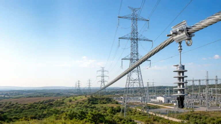
Every overhead line hardware schedule has a long mechanical middle — tension clamps, suspension clamps, joints, dampers — and a short tail of parts that carry no conductor load. Corona rings, grading rings and arcing horns sit in that tail. They are ordered late, drawn as a sketch rather than a dimension, and are the first items dropped when a quote is trimmed. On a distribution structure that changes nothing. On a transmission structure, leaving them off produces no mechanical failure anyone notices; it produces radio interference complaints, noise, corroded fittings, and occasionally a flashover that destroys the fittings the protective hardware existed to shield.
They are also the parts most often mis-installed, because nothing about a toroid or a bent rod looks wrong when it is bolted on backwards. A ring mounted in the wrong plane still tightens down. This guide covers what each family does electrically, where it mounts, which dimensions carry the function, and what to check on arrival and after installation. It quotes no voltage thresholds, gap settings or ring diameters as universal rules: those belong to the project’s insulation coordination study and the manufacturer’s drawing, and a figure carried over from another project is a defect with a delay fuse.
Why a Mechanical Fitting Needs Electrical Protection
A line is designed so the field along the conductor stays below the level at which air breaks down locally. Along a smooth stranded conductor that is achievable. Hardware interrupts the smoothness: a clamp body has edges, a bolt head has a corner, and the line end of an insulator string has a fitting where the yoke plate meets the cap. Each small radius concentrates the field, and the local gradient at a sharp edge can be many times the average gradient along the span.
When that gradient exceeds the breakdown strength of air at the site — corrected by the design calculations for air density, altitude and humidity — the air around the edge stops behaving as an insulator and a localised partial discharge begins. Dry weather suppresses it; rain, fog and humidity bring it out. Three consequences follow.
It radiates. A discharge is a fast current pulse, and a line with many discharge points acts as a distributed noise source. That is what residents hear on AM radio or see as streaks on a television picture, and what a regulator measures when a line is complained about. Audible noise is assessed separately.
It attacks the hardware. Corona in air produces ozone, and ozone with moisture forms nitric acid. On galvanised steel that means accelerated attack on the zinc where the field is highest; on aluminium, pitting, and with chlorides present stress corrosion at a cold-worked section. Polymeric surfaces suffer tracking and erosion, which is cumulative.
It can escalate. Under pollution or an overvoltage, the partly ionised air at a discharge point is where a flashover starts — and if it starts on a clamp body, the arc burns the clamp.
The Three Families and What Each One Does
A grading ring is a toroid, racetrack or elliptical loop mounted around hardware to reshape the field. Its large radius of curvature becomes the highest-field point in the assembly, and because the field at a curved surface falls as the radius grows, the gradient there is far lower than at the bare hardware edge. On a long insulator string it also adds capacitance at the line end, flattening voltage distribution so the unit nearest the conductor no longer carries a disproportionate share.
Corona rings are grading rings used to suppress discharge rather than to grade a string. One part often does both, which is why the names are interchangeable in schedules.
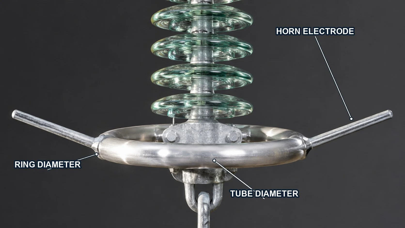
An arcing horn, or protective gap, is a pair of rod or tube electrodes forming a deliberate air gap that is electrically weaker than the insulation it protects. A flashover strikes across that gap and roots on the horn tips instead of the clamp body, insulator cap or conductor. Horns are sacrificial, dimensioned with an erosion allowance so a defined number of operations can be absorbed.
On many transmission assemblies the functions combine: horns bolt to the grading ring so the arc roots on the ring’s outer edge, away from hardware and insulator. It is compact, and it is the arrangement most often assembled wrong, because the brackets physically fit in more than one position.
| Part | Function | Where it mounts | What fails if missing or wrong |
|---|---|---|---|
| Grading / corona ring | Lowers peak surface gradient; grades voltage along a string | Concentric with line-end hardware, plane parallel to the hardware plate | Corona at clamp edges and bolt heads; interference and noise; accelerated corrosion at high-field points |
| Arcing horn / protective gap | Defines where a power arc strikes and roots | Bridging line-end and earth-end fittings, or on the ring’s outer edge | Arc burns on clamp body and conductor; arc root damage to insulator hardware |
| Ring-mounted horn bracket | Combines both functions | Bolted to the ring at the drawing positions | Arc roots close to hardware; ring burnt through where it was not designed for it |
| Ring on terminations and arresters | Controls the field at the top of a vertical stack | Top electrode, coaxial with the stack | Tracking at the top flange; uneven voltage distribution across the stack |
Corona Ring Geometry Is the Specification
A ring is one of the few fittings where the shape is the performance: two rings from the same tube with the same finish behave differently if diameter or mounting height differs. A schedule listing only “grading ring, for tension assembly, qty 6” has specified nothing.
Overall diameter and tube diameter
Overall diameter sets the effective radius the field sees. Increase it and the gradient at the ring drops — but the ring must still fit inside the phase-to-earth clearance and not reduce the strike distance to the tower. The diameter is a clearance calculation result, so a substitute from another supplier is a different electrical component even if the clamp fits.
Tube diameter matters less obviously. A large ring made from thin tube has a small cross-section radius, and that section becomes the sharpest feature in the assembly: the corona moves from the clamp to the ring.
Mounting height and plane
The ring sits in a defined plane — normally parallel to the yoke plate, perpendicular to the insulator axis — at a defined distance out from it. Too close and the field couples to the hardware inside, which still discharges. Too far and the hardware falls outside the shielding envelope. The correct height belongs to the assembly, and it is the dimension most often lost when a drawing is redrawn locally.
Continuity and split construction
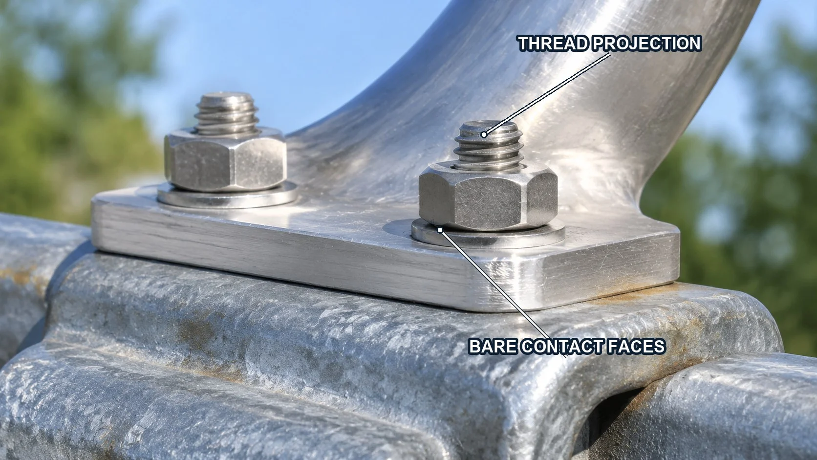
A ring is electrically part of the hardware it surrounds, so the bolted joint must be a real connection: bare metal on both faces, correct bolt grade, torque from the manufacturer’s table. Isolated by paint, heavy oxide or a loose bolt, it floats at an undefined potential — worse than no ring, because the joint gap becomes a discharge point. Split rings allow retrofit without dismantling the assembly, at a cost: the joint is a discontinuity, and both fit and contact there must be right.
Arcing Horns: Setting the Gap and Letting It Burn
A horn works by being the weakest link in a controlled way. The gap is set so a flashover strikes there before it crosses the protected insulation. The arc then burns in open air between two electrodes whose only job is to survive long enough; because the arc root moves along the electrode under magnetic and thermal forces, erosion spreads rather than concentrating at the tip.
Three consequences follow. The gap is an insulation coordination output — not adjustable in the field to look even, not interchangeable between voltage classes. Electrode material and section are part of the design: thinner rod erodes through in fewer operations. And the mounting must survive the arc, which produces a violent pressure pulse able to loosen a bracket tightened by feel.
Horns also interact with the ring. Where both are fitted, the tips define the flashover path and the ring defines the field. Move the horns inboard onto the ring and the arc roots there; mount them on separate brackets and it roots elsewhere. A crew that fits the bracket to whichever hole lines up has changed the electrical design without recording it.
| Drawing item | What it controls | Typical field error |
|---|---|---|
| Horn gap | Where flashover strikes relative to the protected insulation | Gap eased up on site, or set by eye after a bracket was bent |
| Horn orientation | Arc root travel and clearance to steel and jumpers | Horns rotated to clear a rope during stringing, never returned |
| Electrode section and material | Erosion allowance, operations absorbed | Swapped for thinner rod of the same length to meet a delivery date |
| Bracket fixing and bolt grade | Survival of the arc-induced pressure pulse | Reused bolts with damaged threads; no washers on the arc side |
| Position relative to the ring | Whether the arc roots on the ring or a separate electrode | Bracket fitted to the nearest hole rather than the drawing position |
Where These Parts Get Left Out of the Order
Asked why a shipment arrived without the rings shown on the drawing, most suppliers point at the purchase order, and they are usually right. Four gaps do it.
The first is catalogue-driven scheduling. Rings are listed separately from the clamp they mount on, in another section of the same catalogue. A buyer working from the clamp pages produces a complete mechanical order with no protective hardware in it, and nothing in the document looks incomplete.
The second is the split between drawing and bill of materials. The drawing serves installation, the bill of materials serves purchasing, sometimes produced by another person, sometimes from an earlier revision. Parts shown graphically but not itemised are the ones that vanish. The fix: the bill of materials is the only source of quantity, and every drawing item carries an index number that appears in it.
The third is retrofit. When a clamp or damper is replaced, the crew reuses the ring already there — even if the new clamp has a different mounting height, the ring is dented, or its joint faces are corroded. The old ring was matched to the old hardware.
The fourth is voltage-class mixing: a project may hold three structure classes with different assemblies, and compiled per project rather than per class, the cheapest ring gets ordered for everything. Receiving inspection is where this is still caught — counting hardware against the parts list rather than counting cartons, as set out in Incoming Inspection: Checking a Shipment of Line Hardware.
What the RFQ and the Drawing Must State
Protective hardware is easy to specify completely and equally easy to specify ambiguously, because most parameters are dimensions a supplier could reasonably guess. Guessing produces a ring that fits but does not shield.
Each item carries the assembly reference and the clamp model it mounts on — not just the line voltage. Then overall diameter, tube or rod diameter, mounting height, plane orientation, split or solid, material and finish, bolt interface, and quantity by structure class as well as in total. Marking and packing belong in the same document: a mixed carton of rings for three structure classes is a sorting job in the wind.
Verification is worth a line each: dimensions against the drawing, material certificate, finish on contact faces. For aluminium rings, a visual check for dents and weld dressing says more than dimensions alone — a few millimetres of dent is within tolerance and still creates a discharge point.
How to assemble a line-hardware RFQ so suppliers can quote without assuming is covered in How to Specify Overhead Line Fittings in an RFQ. Where the assembly ends in a tension clamp — the usual case for a grading ring — that selection is a separate decision, described in Tension Clamp Types: Compression vs Bolted vs Wedge vs Preformed.
Installation Details That Decide Whether It Works
These parts go on after the conductor is sagged and the assembly is complete, in the same window as dampers and armour rods, because the ring position is defined against a finished assembly. Why the mechanical work comes in that order is set out in Sag, Tension and Stringing: Why Fittings Come Last.
Clean the joint, then torque it
The bracket-to-clamp joint is an electrical connection: both faces cleaned to bare metal, assembled dry unless the specification calls for contact compound, tightened to the manufacturer’s value with a checked tool. A loose joint in a high field is the discharge point the ring was fitted to remove.
Respect the plane
The most damaging error is rotating the ring out of plane — parallel to the insulator axis, or tilted to clear a jumper. It fails nothing mechanically and is not obvious in a photograph from below. It simply stops grading, and the corona returns to the hardware.
Keep fastener projections out of the field
Thread ends, split pins and washers projecting beyond the nut are small-radius features in the highest-field region, which is why drawings specify bolt orientation. A sawn thread is a row of sharp edges and is dressed, and capped where specified.
Do not straighten a dented ring
Aluminium dents in handling. A dent changes local curvature and collects water and contamination; both are corona-friendly. A dropped ring that has been straightened has not been restored to its geometry and should be rejected — as should a horn bent to fit, since gap and arc path both change.
Clearances get a final check after everything is on: ring to steel, ring to the adjacent phase under wind swing, horn tips to the jumper. Protective hardware is often the last item fitted and the first damaged by the next crew on the structure.

Inspection and What the Evidence Looks Like
Two questions are asked of these parts: whether they are still doing their job, and whether they have already absorbed an event.
Condition first. Powdery white or grey deposits on aluminium indicate sustained discharge; tracking and pitting at the ring weld point the same way; fretting and rust staining at bolted faces indicate movement; horn erosion is measured against the manufacturer’s limit, not compared with the other side of the structure.
Performance is measured, not looked at. Corona is strongest in damp conditions, so a night patrol in fog, or a solar-blind ultraviolet camera, shows discharge points a visual check misses. Radio interference surveys at fixed points produce a trend comparable year on year; audible noise follows its own procedure and standard.
Thermal imaging has a narrower role here: a discharge does not necessarily produce a temperature rise an infrared camera will see, but a bad electrical joint — a loose ring bracket, a corroded contact face — will show. When a hot spot is reported at a protective fitting, the fault is in the bolted connection, not the ring’s function. The method is described in Infrared Thermography for Line Joints: Finding Hot Spots, and the wider routine in Overhead Line Fittings Inspection.
Records turn inspection into a decision: a photograph of each assembly, horn gap, remaining horn length, date, structure number and ambient condition. Six fields tell normal erosion from a structure flashing over repeatedly; without them, replacement is decided on impression.
Materials, Interfaces and Corrosion
Rings are normally aluminium tube with aluminium or stainless brackets; horns are galvanised steel rod or aluminium tube. Both put dissimilar metals against galvanised steel, and that interface is where corrosion starts: aluminium against zinc in moisture forms a galvanic couple, and the aluminium — the ring — gives way. Stainless fasteners help at the bolt but do not remove the couple at the contact face.
The measures are the usual ones: clean and, where specified, sealed contact faces; correct-grade fasteners; drainage so water does not stand in the bracket or in a horizontal run of tube. On coastal and industrial routes these details decide service life, and the wider comparison is in Line Fitting Materials: Galvanised Steel, Aluminium, Stainless.
Corona by-products make this worse: nitric acid from ozone and moisture concentrates where the field is highest, so a discharging ring corrodes faster than its neighbours, and the deposit seen in inspection is both symptom and cause. Painting is not the answer — it hides cracks, changes the surface the field calculation assumed, and can leave an insulating layer at the joint.
Frequently Asked Questions
Can corona rings be retrofitted to a line already in service?
Physically yes — split rings fit an existing assembly without dismantling it. The decision is not a purchasing one: whether a structure needs a ring, and at what size and height, comes from that line’s insulation coordination study, not from comparison with a neighbouring route.
Does fitting a corona ring always reduce radio interference?
Only when it is the right ring, in the right plane, at the right height, with a sound joint. An undersized ring, one mounted out of plane, or one isolated by a painted contact face can add a discharge point at its own joint instead.
Are arcing horns reused after they have operated?
They are inspected against the manufacturer’s erosion allowance — not automatically replaced, not automatically reused. The tips erode with each operation and remaining length decides whether the gap still performs; a horn reduced below the limit is finished, and bending it straight does not restore it.
How do we decide which structures need grading hardware?
From the insulation coordination study, which weighs system voltage, altitude, pollution level, switching and lightning overvoltage, and the geometry of the assembly. Two lines at the same nominal voltage can differ, which is why a schedule listing protective hardware by voltage class alone is not a specification.
Closing the Last Item on the Schedule
Protective hardware is a small fraction of the value of a line hardware order and a large fraction of its electrical performance. These parts carry no conductor load, which is why they are easy to treat as optional — but an assembly is designed as a field distribution, not only a load path: the clamp holds the conductor, and the ring and horn decide whether the clamp survives the voltage around it.
The discipline is short: put these parts in the bill of materials as numbered items with their own quantities, treat diameter, tube size, mounting height and plane as functional dimensions, count them against the parts list on arrival, check plane and joint torque after installation, measure the horns at every patrol. None of it needs new equipment, and all of it is cheaper than a burnt clamp on a structure meant to be maintenance-free for its design life.
For enquiries on tension and suspension assemblies and the protective hardware that goes with them, send the assembly drawing with the clamp model, ring dimensions and quantities by structure class; the load-bearing half is covered on our tension clamp and suspension clamp pages, the field-side checks in suspension clamp failure causes and field checks, and the spacing hardware sharing the same span in Spacers and Spacer Dampers for Bundled Conductors.