
Spacers and Spacer Dampers for Bundled Conductors
A bundled conductor solves one problem and creates another. Splitting a phase into two, three, four or more sub-conductors raises the effective diameter of the phase, which cuts corona loss and audible noise, and lowers reactance, which is why most lines above a certain voltage use bundles. The moment those sub-conductors hang side by side in a span, they start to interact. Magnetic forces pull them together during a fault, wind drives them into oscillation, and ice or uneven tension changes the shape of the bundle along the span. A spacer holds the designed geometry. A spacer damper holds the geometry while also absorbing the energy that would otherwise fatigue the conductor at the clamps.
This article is written for the people who buy, install and maintain these parts: what a spacer actually does, how the three mechanical families differ, which datasheet fields decide fit, how positions are arrived at, what crews get wrong, and how to judge an installed unit from the ground.
Why a Bundle Needs Spacers at All
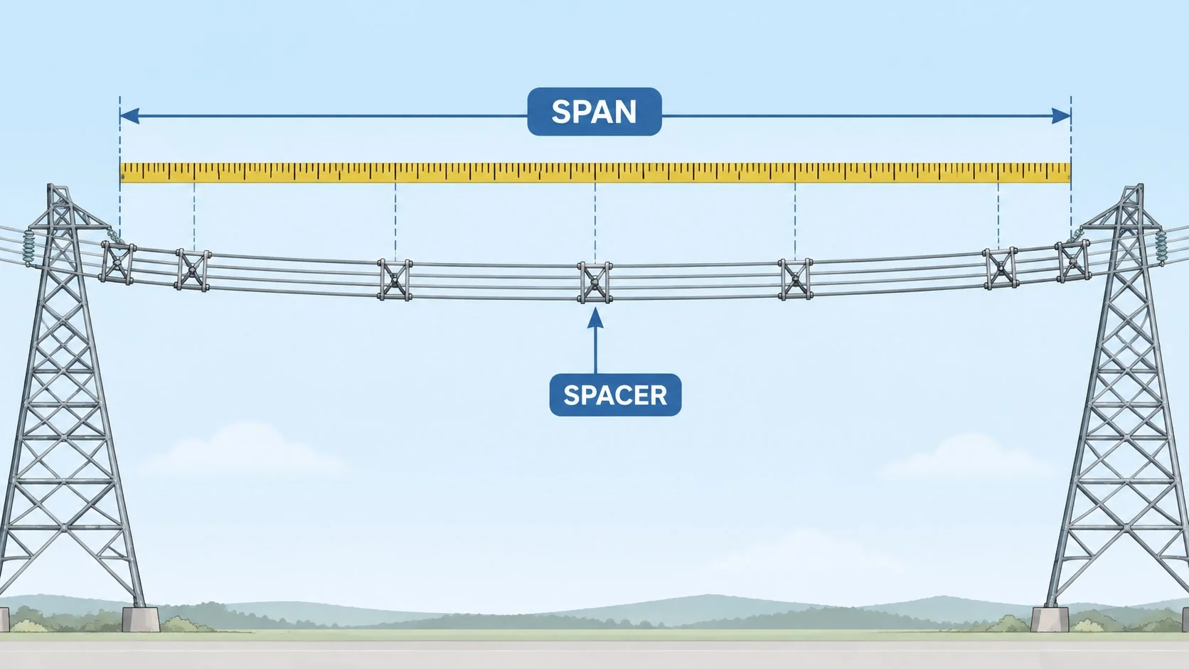
A bundle is not a rigid body. Each sub-conductor is a separate wire rope under its own tension, and the only thing tying them together is the hardware clamped onto them. Between clamps, each one vibrates, swings and sags according to its own tension, ice load and wind exposure. Nothing keeps them at the designed spacing unless a component does that job.
Short-circuit pinch
During a fault, current flows the same way through all sub-conductors of a phase. Parallel currents in the same direction attract, so the bundle collapses inward and springs back when the fault clears. The frame and clamps have to carry that pinch and rebound without permanent deformation, without slipping along the conductor, and without delivering a damaging bending moment into the aluminium strands. This is why short-circuit withstand appears on the datasheet as a design case, with the current and duration it was checked against.
Wind-induced movement
Wind does not simply push the bundle sideways. It sheds vortices from the leeward side of each sub-conductor, and in a bundle the wake of one conductor reaches the next. The result is a family of motions: aeolian vibration at high frequency and low amplitude, sub-span oscillation where the bundle rocks and sub-conductors trade places, and galloping under extreme icing. Spacers change all of it, because they divide a long span into shorter sub-spans with their own natural frequencies, and because a damped unit turns some of the motion into heat instead of passing it into the clamp. The mechanics are set out in this explanation of aeolian vibration; what matters here is that the spacer is part of the cure, not an accessory.
What happens when the bundle is left unsupported
Without spacers over a long span, the sub-conductors close up in the middle, touch, and separate again, thousands of times. Aluminium is soft, and fretting between two conductors removes material without any visible spark, leaving flattened and eventually broken outer strands. By the time the damage is visible from a bucket truck, tightening a bolt is no longer the fix; it becomes a conductor repair job. Clashing also wears the liners of the tower hardware and, in the worst case, produces flashover between sub-conductors of the same phase.
Three Mechanical Families: Rigid, Flexible and Damped
The three families are often presented as grades of one product, with “damped” being the best. That is a poor way to buy them. They solve different problems, and each has a failure mode the others do not have.
Rigid spacers
A rigid spacer is a fixed frame — usually a square or triangular aluminium frame, sometimes a forged body — with a clamp at each sub-conductor position and essentially no relative movement between conductors. It is simple, inexpensive and gives a predictable bundle geometry. It suits short spans, compact distribution bundles at modest tension, and substation bus where spans are short and vibration is not the governing load. Its weakness is that every movement of the bundle is resisted at the clamp, so the conductor takes the strain at the clamp edge. Once the liner hardens or the clamp is over-tightened, abrasion starts there.
Flexible and spring spacers
A flexible spacer introduces articulation: hinged joints, or arms in spring steel, so the frame opens and closes slightly instead of fighting the bundle. This lowers the bending stress delivered to the conductor and tolerates small errors in bundle spacing and clamp position. The trade-off is less restraint against sub-span oscillation, and a dependence on the spring elements keeping their properties. Where arms are elastomer-bonded, the bond line is the part to watch.
Spacer dampers
A spacer damper keeps the geometry of a rigid frame but adds a damping element — elastomer block, friction joint or tuned viscoelastic assembly — at the clamps or in the articulated arms. It is built for the combination that matters on high-voltage lines: hold the design spacing, allow controlled relative movement, and dissipate vibration energy before it reaches the conductor. That is why spacer dampers are standard on EHV and UHV bundles, and why their datasheets carry a damping specification as well as a mechanical one. They are also the family where installation detail matters most, because a damping element pre-loaded by a misaligned arm no longer behaves as tested.
| Family | Relative movement allowed | Typical use | Characteristic failure mode |
|---|---|---|---|
| Rigid spacer | None; frame fixes the bundle | Short spans, compact LV/MV bundles, substation bus | Conductor abrasion and strand fatigue at the clamp edge; frame cracks at welded corners |
| Flexible / spring spacer | Limited, through hinges or spring arms | Medium spans, bundles with tight alignment tolerance | Spring or elastomer bond loses stiffness; arm takes a permanent set |
| Spacer damper | Controlled, with energy dissipation | EHV/UHV transmission bundles, long spans, high wind exposure | Damping element fatigue or hardening; clamp grip loss; pin and bolt loss |

Reading a Spacer Datasheet
Most ordering mistakes are not made in the drawing office. They are made when a purchase order is raised from a short description — “four-bundle spacer damper, suit ACSR” — without checking the fields that decide fit.
The first is the clamp. A spacer clamp is not a suspension clamp and cannot be chosen by nominal conductor size: it has to match the actual outer diameter of the sub-conductor, including any armour rods or line guards that will sit under it. A clamp sized for the bare conductor will not close over a rod, and one sized for the rod will rattle on the bare conductor elsewhere on the line. The second is bundle geometry: sub-conductor spacing and the resulting bundle circle are design values, not preferences. A unit built for a different spacing either pulls the bundle out of shape or cannot reach the outer conductors. The third is loading: grip or slip load, short-circuit withstand and mechanical failing load each answer a different question, and a datasheet quoting only one of them is incomplete.
| Datasheet field | What it tells you | If it is wrong |
|---|---|---|
| Conductor diameter range per clamp | Whether the clamp closes on the actual sub-conductor, with or without armour rods | Loose clamp slips and abrades; oversize clamp will not seat and pinches strands |
| Sub-conductor spacing / bundle circle | The geometry the spacer will hold | Bundle pulled out of shape; greater risk of clashing elsewhere in the span |
| Number and arrangement of clamps | Bundle configuration (2, 3, 4, 6, 8) | Unit cannot be installed, or leaves one sub-conductor unrestrained |
| Grip / slip load | Axial force the clamp carries before it moves | Spacer migrates along the span and the spacing schedule is lost |
| Short-circuit withstand | Fault case the frame and clamps were checked against | Permanent deformation or clamp slip after a through-fault |
| Arm and frame material, galvanising | Corrosion life in the actual environment | Coating failure at joints and threads within a few years |
| Damping element type and temperature range | Whether damping is elastomer, friction or tuned mass, and where it stays valid | Element hardens or creeps; damping disappears with no visible damage |
| Overall dimensions and weight | Installation method and handling on the bundle | Crew cannot manoeuvre the unit; extra conductor load during installation |
| Corona provision | Whether the profile was checked for corona at line voltage | Audible noise and radio interference complaints after energisation |
How Positions Along the Span Are Decided
The spacing schedule is not a rule of thumb and should never be improvised on site. It comes from a calculation that takes conductor diameter, bundle spacing, tension, span length, terrain category and expected wind climate, and derives sub-span lengths that keep the bundle’s vibration response under control. Different manufacturers run it with their own programs, and utilities often have their own preferred schedule; both are legitimate but not interchangeable, and a schedule copied from a similar line at a different tension is not a schedule.
The crew receives a drawing with positions marked as distances from a reference point, usually a suspension or tension clamp, and the job is to reproduce those positions accurately. Two rules matter more than the rest: end spacers sit close to the hardware, where the conductor is least restrained and the bundle shape most likely to distort, and the sub-spans should come out roughly equal, because an uneven schedule leaves one long sub-span with a low natural frequency exactly where wind can excite it.
Two constraints override the drawing when they conflict with reality. Spacers should not be clamped over a joint, a repair sleeve or the end of a set of armour rods, because the clamp cannot seat on an uneven surface and the joint beneath it will then be hidden from inspection. Where the line carries marker balls or other attachments, positions have to be shifted to suit, and that shift should be agreed with the design office rather than decided from the basket. Conductor damage found while marking is a separate issue: it needs assessment before the spacer goes on.
Installation: What Crews Actually Get Wrong
Almost every spacer problem found in service traces back to one of five errors, and all five are avoidable with a short pre-job briefing.
Wrong position, accepted
Positions measured with a rope and estimated by eye drift, especially on long spans where the reference mark is far away. The result is a schedule that looks approximately right and behaves like a different design. A template or measuring wheel, plus recording actual positions against the drawing, costs a few extra minutes per span.
Clamp not seated
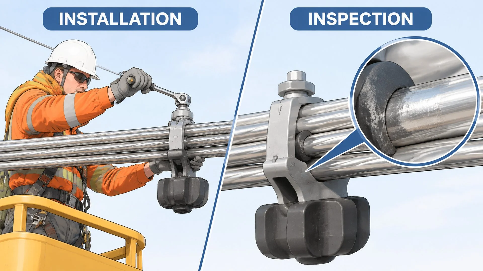
The conductor must sit fully in the groove, liner in place, strands not spread. A clamp closed over a spread bundle, or with the liner displaced, holds initially and slips later. With armour rods, the rods must be centred under the clamp, not caught at their end.
Torque guessed
Bolts tightened by feel, or with a wrench that has never been calibrated, cause both loose clamps and crushed conductors. The correct value is the one in the manufacturer’s installation sheet for that model and bolt size, applied with a calibrated tool and checked afterwards. It should never be taken from a similar product, and never increased because a bolt felt loose.
The spacer used as a tool
Spacers get stood on, used as a handhold, and used to pull the bundle into position. A frame designed for short-circuit pinch is not designed for a person’s weight applied at one arm, and a bent arm changes the damping behaviour of the whole unit. Platforms and bundle boards exist for this reason.
Alignment ignored
Each arm must sit so the bundle stays in its designed shape, clamps square to the conductor. An arm forced into place pre-loads the damping element or the hinge, and the unit then behaves as a rigid, over-stressed spacer. On four-bundle lines this shows as a rotated bundle, one sub-conductor riding high and another low, visible from the ground with binoculars.
Inspection and Replacement Criteria
Spacers are checked in the same walk or drone pass used for the rest of the hardware. The reference for judging them is the maintenance standard of the utility or the manufacturer’s maintenance manual; the checks below are what those documents generally ask for.
Start with geometry. Sub-conductors should be evenly spaced along the span and the bundle should not be rotated. A gap that closes mid-span, or a bundle that looks twisted, points to a slipped, missing or bent spacer. Then each unit: bolts and pins present and locked, arms straight, liners in place, damping elements free of cracks, extrusion or corrosion products. Look at the conductor either side of each clamp for abrasion marks, flattened strands or a polished band — the signature of a clamp that has been moving.
Decisions fall into three groups. A unit with a missing bolt or pin, a bent arm or a visibly failed damping element is replaced at the next planned outage. A unit that has slipped along the conductor is repositioned and re-clamped, and the reason investigated, because a slip on one unit often means a batch was under-torqued. A unit that is intact but sits next to conductor damage stays until the conductor condition is assessed, since removing it changes the loads on the remaining spacers in the sub-span.
| Symptom seen in the field | Likely cause | Action |
|---|---|---|
| Spacer missing from a marked position | Clamp slip, bolt loss or mechanical damage | Record position, replace at outage; check neighbours for a batch problem |
| Bundle closes up mid-span | End spacers slipped or fitted at the wrong distance | Re-mark and reposition per drawing; verify torque with a calibrated tool |
| Polished band or flattened strands at the clamp | Clamp movement, hardened liner or over-torque | Assess the conductor against repair criteria before re-clamping |
| Cracked or extruded elastomer | Ageing, ozone or pre-load from misalignment | Replace the unit; check arm alignment on the replacement |
| Bundle rotated, one conductor riding high | Arm forced during installation, or one arm damaged | Re-align or replace; inspect adjacent units in the span |
| Arc marks on frame or clamps | Flashover between sub-conductors or to earth | Engineering assessment, not routine replacement |
Specifying and Buying Spacers
An enquiry that states only “four-bundle spacer damper, quantity required” produces quotations that cannot be compared, because each supplier assumes a different spacing, diameter range and test basis. The minimum that makes offers comparable is the same discipline described in how to specify overhead line fittings in an RFQ.
Give the conductor: code name or full designation, nominal area, stranding and actual outer diameter, and whether armour rods or line guards will sit under the clamps, with the resulting outside diameter. Give the bundle: number of sub-conductors and design spacing. Give the electrical duty: system voltage, and the short-circuit current and duration the line is protected at. Give the mechanical duty: span range, tension at the relevant condition, ice and wind loading to be covered. Give the environment, because coastal, industrial, desert and clean inland decide the galvanising and hardware finish. Finally state the inspection regime — type test reports, routine test certificates, material traceability, third-party inspection — and how the goods must be marked and packed.
Three things separate a serious quotation from a catalogue page. Whether the supplier quotes against the diameter you gave rather than a nominal range. Whether type test reports exist for that design and can be produced, rather than a general statement that the product has been tested. And whether the installation sheet states a torque value for each bolted connection, because a supplier who cannot state it has not defined the product fully. On arrival the same discipline applies as in incoming inspection of line hardware: check dimensions, coating and thread condition, and photograph anything that may become a claim.
Where Spacers Sit in the Rest of the Fitting Set
Spacers are one item in a set that has to work together, and they are the item most often left off a bill of material because they are neither structural nor shown in a single-line diagram. On a bundled line the suspension or tension assembly holds the phase, the spacer holds the bundle, and a damper controls vibration in the conductor itself.
It helps to link the pieces when writing a specification. The tower clamp is chosen in this guide to suspension clamp selection and installed per the suspension clamp installation procedure; the bundle hardware sits between those clamps and is described in aerial bundled cable fittings. Condition of the whole set is judged in the overhead line fittings inspection routine, and the patterns it looks for are set out in these field checks on suspension clamp failure causes. For the wider picture of what each component does, the overview of overhead power line components is a reasonable starting point for a new buyer.
Frequently Asked Questions
How many spacers does one span need?
There is no universal count. The number follows from the spacing schedule, calculated from conductor diameter, bundle spacing, tension, span length and wind climate. A supplier quoting a number without those inputs is guessing. Ask for the schedule that goes with the design, and check the drawing supplied with the shipment matches it.
Can spacers be added to an existing line without re-stringing?
Yes, in most cases. Units are installed from a bundle basket or insulated platform, with the line de-energised or worked to the utility’s live-line procedure, and the conductor is not disturbed beyond the clamp area. Two conditions apply: the conductor at the clamp position must be sound — no joints, no repair sleeves, no strand damage — and the sag must still correspond to the original design, because a line that has crept will not follow the original schedule.
Does a spacer damper replace a Stockbridge damper?
No. They address different motion. A spacer damper controls the relative movement of sub-conductors and adds damping to the bundle’s own modes. A Stockbridge damper is mounted on the conductor to control aeolian vibration in a specific frequency band, and on bundled lines is often fitted as well, usually near the clamps. Fitting one does not make the other unnecessary.
How can I tell whether a clamp has lost grip?
Look for a polished or abraded band on the conductor at the clamp edge, a spacer that has moved from its marked position, or uneven spacing along the span. Grip is confirmed by test on a sample, not by eye, which is why grip or slip load belongs on the datasheet and should be supported by a test report rather than assumed.
If you are specifying bundle hardware for a new line or replacing units on an existing one, start with a short data sheet of your own: conductor and rod diameters, bundle configuration and spacing, voltage, fault level, span and tension range, environment, and the inspection you require. Send that with the enquiry and the quotations you get back will be comparable. Our suspension clamp range and the bundle hardware that goes with it are quoted against exactly those inputs, and can be matched to an existing spacing schedule where one already exists.