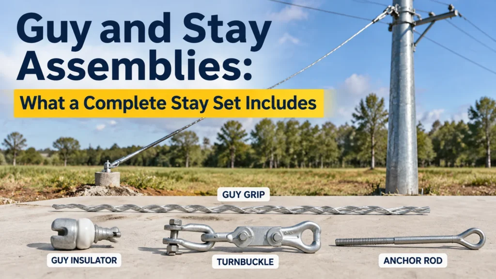
Guy and Stay Assemblies: What a Complete Stay Set Includes
A guy wire is only as strong as the weakest fitting threaded onto it. On an overhead line, the guy does not work alone: it transfers the entire lateral load of a pole, a corner, or a dead-end into the ground through a chain of hardware, and every link in that chain — anchor rod, strand, grip, turnbuckle, insulator, guard — has to be specified as one matched set. When crews order “a guy kit” as a loose collection of parts picked from three different suppliers, mismatched strength ratings and thread sizes are the usual result.
This guide walks through what a complete stay set actually includes, what each component contributes, how the pieces are selected so they share the load evenly, and what to look for during installation and inspection. It is written for purchasing teams and site engineers who specify line hardware for distribution and sub-transmission projects, not for installers looking for step-by-step torque values — those always come from the fitting manufacturer’s data sheet and the project specification.
Why Lines Are Guyed, and What the Assembly Must Resist
Every pole structure in an overhead line is a cantilever beam. Wherever the conductor loads stop being balanced — at dead-ends, at line angles, at crossings and terminal poles — the unbalanced tension has to go somewhere, and it goes into guys and stays. A single distribution dead-end can pull with several tonnes of horizontal force, far more than a pole can resist on its own.
That load path matters for specification. The guy assembly is loaded in pure tension, and its rated breaking load must be matched across every component. The strand, the grips at both ends, the turnbuckle, and the anchor rod each carry the same force, so a single underrated part de-rates the entire assembly. Strength matching, thread compatibility, and material compatibility are the three things to verify before anything is shipped to site.
If you are new to how these loads arise across a whole line, the overview in our guide to overhead power line components explains where tension, angle and dead-end loads appear along a route, and how each structure type deals with them.
The Components of a Complete Stay Set
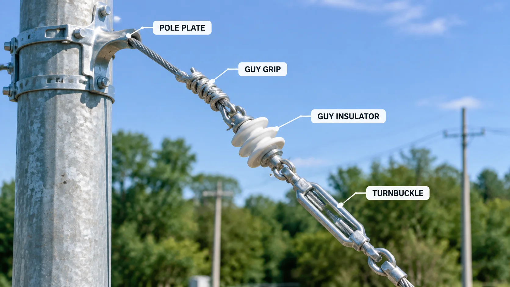
A full guy assembly runs from the pole to the buried anchor, and each element has a distinct job. The table below lists the parts in load order, from the pole attachment down to the earth, and what you need to confirm at the ordering stage.
| Component | Function in the assembly | What to verify when ordering |
|---|---|---|
| Pole plate / guy attachment | Spreads the guy load into the pole or crossarm without crushing the wood or concrete | Bolt size and pull-through load match the pole class; curved or flat seat suits the pole surface |
| Guy strand | Carries the working tension from pole to anchor | Rated breaking load covers the design load with the project safety factor; galvanising class suits the environment |
| Dead-end grip (top) | Terminates the strand at the pole end | Rated for the exact strand diameter and lay; wedge socket, preformed grip or compression sleeve as specified |
| Guy insulator | Breaks the electrical path between the live line side and the grounded anchor | Voltage class and creepage distance match the system; mechanical rating matches the strand |
| Turnbuckle or guy eye-nut | Joins the lower strand termination to the anchor rod and allows tension adjustment | Thread diameter and direction match both sides; safe working load equals the strand’s |
| Anchor rod and buried anchor | Transfers the final load into the soil | Rod diameter, length and anchor type (plate, screw, concrete) match the soil class calculated for the site |
| Guy guard and marker | Protects the public from the grounded guy and makes it visible | Length covers the zone from ground level to above head height; colour per local road authority rules |
Two parts of that chain deserve a closer look, because they are where mismatched ordering shows up first: the termination hardware and the anchor itself.
Anchors and Anchor Rods: Where the Load Enters the Ground
The anchor is the only component whose capacity depends on something you cannot see — the soil. The same plate anchor that holds at a calculated load in stiff clay can fail at a fraction of that in soft silt or fill material. Soil class, not the hardware catalogue, determines whether you use a driven plate anchor, a screw anchor, or a cast concrete deadman, and at what depth and angle of installation.
When ordering anchor rods, the points to check are rod diameter and thread length, the shape of the tangent on the rod eye, and the galvanising thickness. The rod thread has to engage the turnbuckle or guy eye-nut for its full length after final tensioning — a thread that bottoms out before the assembly is tight is a common site defect that no amount of wrench force will fix. Because these are structural parts of the same load chain, they should be specified together with the strand and grips in one RFQ package, the way we describe in how to specify overhead line fittings in an RFQ, rather than sourced piecemeal.
Guy Strand and Grips: Three Ways to Terminate Steel
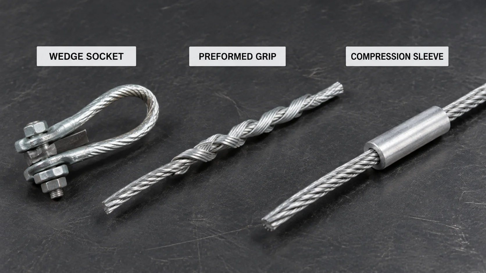
Galvanised steel strand is the tension member of nearly every stay set. Terminating it is not a matter of preference but of matching the termination type to the strand, the load, and the installation crew’s tooling. The three families in common use are:
- Wedge sockets. The strand loops around a steel wedge seated in a socket body. They are re-usable and quick, but the loop must be formed with the correct tail length and the wedge must match the strand diameter exactly, or the holding efficiency drops sharply.
- Preformed guy grips. Helical rods wrapped by hand over the strand; the tension itself tightens the wrap. There is no tooling beyond a measuring tape, and the grip is factory-matched to one strand size. Our guy grip guide covers how these are sized and installed, so we will not repeat the selection detail here.
- Compression dead-ends. A sleeve pressed onto the strand with the same hydraulic tooling used for conductor joints. Highest and most consistent holding strength, but requires calibrated press equipment on site, which is why they appear more often in contractor-serviced networks than in simple distribution builds.
Whatever the type, the rule is the same: a grip is rated against a specific strand construction and diameter, and substituting a “close enough” size is the single most common cause of slip failures in guy assemblies. Where the project uses helical terminations at both ends of a tension member, the same logic governs other preformed hardware, as explained in our article on tension clamp types compared, which covers how wedge, bolted and preformed dead-ends achieve grip on conductors.
Turnbuckles and Adjustable Guy Fittings
Between the lower grip and the anchor rod sits the fitting that lets the crew set the final tension: a turnbuckle, or in some markets a guy eye-nut and stud combination. The turnbuckle body has left-hand thread on one end and right-hand on the other, so rotating the body draws both ends in together. That geometry is also why mismatched threads destroy themselves — a left-hand eye forged for one rod series will thread part-way onto a similar-diameter right-hand rod and then gall under load.
Specification points for adjustable fittings are straightforward: matching thread diameter, pitch and hand on both ends; a safe working load equal to the strand’s; and enough thread length to give the crew real adjustment range after the strand is cut to length. Check the working-load-to-break-load ratio required by the project specification rather than assuming a generic factor — different utilities specify different safety factors for guys, and the fitting certificate has to reflect the one your project uses.
One practice worth planning for: order turnbuckles with locknuts or plan for a secondary locking device. Vibration over the years walks unsecured turnbuckle bodies open, and a slack guy at a line angle shifts load onto structures that were never designed to take it alone.
Guy Insulators: Breaking the Electrical Path
Every guy that attaches anywhere near live conductors needs an insulator in the strand so that a broken or slipped conductor cannot energise the full length of the guy and its buried anchor. Depending on the system voltage and local practice, that insulator is placed in the stay at a defined height above the reach of people at ground level, or in the lead above the guy for pole-top arrangements.
The insulator has to satisfy two independent ratings at once. Mechanically, it is just another link in the tension chain, and its rated load has to match the strand. Electrically, its voltage class, creepage distance and shed profile have to match the environment — in polluted or coastal air a short-creepage insulator will track and fail long before its mechanical limit is approached. Where the whole line runs in aggressive atmospheres, the same environment-driven selection logic applies to every fitting, which is the subject of our suspension clamp and hardware corrosion guidance for coastal sites.
For lower-voltage distribution, many networks use a “break-off” style insulator designed to fracture cleanly if the guy is over-tensioned, dropping the line-side part of the stay away from the live conductors. If your specification calls for these, confirm that the fracture rating coordinates with the assembly’s design load — too low and it snaps in service; too high and it provides no protection at all.
Guy Guards and Visibility Marking
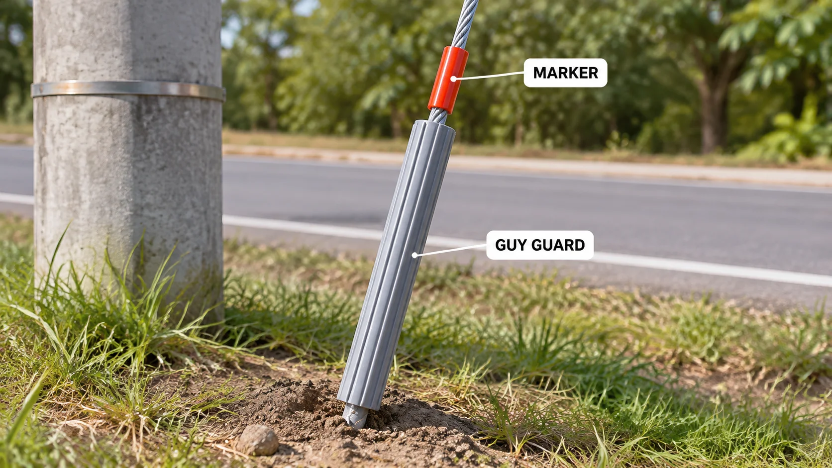
The lowest few metres of a guy are a public hazard: a grounded steel strand at head height beside a road or footpath is invisible at dusk and unforgiving to anyone who walks or drives into it. Guy guards — plastic or PVC sleeves, usually grey, olive or bright colours depending on local rules — shroud that zone. Some designs also include a barrier layer that keeps the buried part of the anchor rod region isolated.
Ordering details that matter here are length (the guard must cover from just above grade to the height set by the local road authority, typically well above pedestrian head height), inner diameter (it has to slide over the guy’s grip tail and thimble without binding), and UV-stabilised material, because guards that chalk and crack in sunlight defeat their own purpose within a few seasons. Colour requirements differ between road authorities, so treat the marker colour as a project-specific line item, not a default.
Installation and Tensioning: Order of Operations
Getting a stay set right on site is mostly about sequence. The anchor goes in first, installed at the specified depth and lead distance so the guy meets the rod at the designed angle — a guy pulled at the wrong angle changes the load on every component in the chain. The strand is then cut with allowance for the grip tails, terminated at both ends, and the turnbuckle is set near its mid-position before tensioning, so the crew has adjustment in both directions.
Final tensioning brings the assembly to the design load stated in the project documents, applied by the specified tool — never by guessing. Use the tension values and tools required by the fitting data sheets and the project specification, and re-check the pole plumb after tensioning rather than before. On jointed assemblies, run through a pre-service check of thread engagements, locknut positions, and grip tail lengths before the crew leaves the structure.
One failure pattern worth flagging: crews sometimes tension the guy to “straighten the pole” instead of to the design load. That over-tension transfers load into the pole in the opposite direction and can lift the anchor over time. If the pole needs raking, that is a setting decision made before tensioning, not a correction forced through the stay. For the broader discipline of reading pole and hardware condition after the line is energised, our overhead line fittings inspection article covers the field routine.
Inspection: What Fails and What to Do About It
Guys fail slowly and then suddenly. Corrosion works from the soil line upward on the anchor rod; strands break one wire at a time from vibration and abrasion near the grips; turnbuckles loosen over years of cyclic load; and in some regions copper-bearing parts and even whole guy sections are stolen for scrap. A routine that catches these early is cheap; one that catches them late pays for pole replacement.
| What to check | Warning signs | Action |
|---|---|---|
| Strand near grips and thimbles | Individual broken wires, abrasion flats, rust staining at the wrap | Count broken wires against the project’s replacement criterion; re-terminate or replace the section when the count is reached |
| Anchor rod at and below the soil line | Section loss, rust scale, soil subsidence around the rod | Excavate to inspect per the utility’s interval; replace rods with measured section loss per project criteria |
| Turnbuckle and threads | Body walked open, locknut loose, thread galling or exposed bare thread | Re-tension to the specified value, reset the locknut, and log the adjustment |
| Guy insulator | Tracking marks, chipped sheds, fractured break-off insulator | Replace the insulator; re-verify the electrical rating against the system before re-energising the stay |
| Guards and markers | Cracked or chalked sleeves, missing sections, faded colour | Replace the guard; treat missing visibility marking as a public-safety priority item |
| Overall assembly | Missing sections (theft), slack guy, pole leaning off plumb | Treat as an urgent defect: de-tension or barricade until the stay set is restored |
Photograph and record every guy assembly at commissioning — anchor type, rod length, strand size, grip type, design tension — because the crew that has to repair it in year fifteen will otherwise be guessing. The same documentation discipline is why we recommend a formal receiving check when hardware arrives on site; the routine is described in our article on incoming inspection of line hardware.
FAQ
What is the difference between a guy and a stay?
In most usage the two terms describe the same thing: an inclined tension member tying a structure to the ground. “Stay” is more common in British and Commonwealth practice, “guy” in North American practice, and some utilities use “stay” for the smaller assemblies used on intermediate poles and “guy” for heavy dead-end assemblies. Functionally, both are tension links and both need the same complete set of hardware described in this article.
Can I mix grip types at the two ends of one guy?
Yes, and it is common — for example a preformed grip at the pole end and a wedge socket at the anchor end where re-use is planned. The requirements are that each grip is individually rated for the exact strand, and that the turnbuckle adjustment range is calculated for the tail lengths of both termination types. What you cannot mix is ratings: both grips must meet the same assembly working load.
Why does the guy insulator sit at a specific height?
So that the grounded portion of the stay below the insulator cannot be reached by the public while the live portion above it is out of reach. The exact height is set by the utility or local safety code and depends on the system voltage and whether the stay runs beside a public way. Treat it as a dimensioned project requirement, not a field estimate.
How do I know if an anchor is adequate for my soil?
Anchor capacity is calculated from soil classification and verified by test installation or pull testing on site. The hardware rating is only an upper bound — the weaker of the anchor’s soil capacity and the hardware’s rating governs the assembly. Where soil information is thin, screw anchors installed with torque monitoring give a continuous indication of capacity that plate anchors cannot, and many engineers specify pull tests for the first anchors of a project.
What should a complete guy kit include when ordering?
All matched-load components from the pole plate down: strand, both terminations, insulator if required, turnbuckle with locking, anchor rod, anchor, thimbles, fasteners, and guards with markers. Order them as one assembly against one design load, with the environment and the local road-authority marking rules stated on the purchase order. Anything ordered “to site’s choice” is where mismatches creep in.
Specifying stay sets as complete, load-matched assemblies is one of the cheapest ways to buy long-term reliability on an overhead line. If you are planning a project and want the component lists checked against your conductor tensions and soil conditions, gather the design loads, environment, and marking requirements first — then send the specification to the supplier as one package, the same way you would for the line’s tension and suspension hardware.