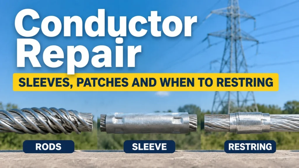
Conductor Repair: Sleeves, Patches and When to Restring
A damaged conductor rarely fails at the moment somebody spots it. It fails later, when load, wind, or a temperature swing pushes a strand that has already lost part of its section past what it can carry. The decision after a patrol report is therefore not simply “fix it or leave it”, but a graded one: what kind of damage is present, how much of the section is affected, where it sits in the span, and whether the repair method on site restores what the conductor was specified to carry.
This article covers repairing an existing, already damaged conductor, not making a planned joint in a new build. Planned splicing is covered separately in our guide to aluminium conductor joints. Here the case is unplanned: broken, burnt, or deformed strands found on patrol, after a lightning event, after external contact, or during a clamp inspection. Any figure, tolerance, or acceptance limit is deferred to the model’s specification sheet, the project specification, or the utility’s maintenance rules. Nothing here replaces those documents.
What the Damage Report Must Capture Before You Choose a Repair
A repair decision is only as good as the report behind it, and most bad decisions trace back to a note that says “strands broken near the clamp” and nothing else. Before a kit is opened, the crew needs a description another person could act on without seeing the site. Record the line and span identification, the position within the span and its distance from the nearest fitting, and the conductor designation, diameter, and stranding read from the specification sheet rather than estimated by eye. Note whether the conductor has a steel core.
Then describe the damage. How many outer strands are broken, and are the ends clean, frayed, or burn-marked? Is it one short zone or several? Is there flattening, birdcaging, corrosion product, or a groove suggesting hardware contact? Photographs should include a scale or fixed reference so a later inspection can compare like with like. On aluminium, note any sign of heating: annealed strands can look intact while no longer carrying what the specification assumes. Record the condition of the hardware on either side too — a repair that leaves the fitting that caused the damage in place will generate the same report again. Our notes on suspension clamp failures and field checks cover the patterns worth checking on the fitting itself.

Damage at a fitting is a different problem
Damage where a conductor leaves a clamp, dead-end, or damper is not the same as free-span damage. The conductor is restrained there, so bending and fretting concentrate in a short length, and the fitting may be the cause. Repairing the strands without correcting clamp alignment, armour rods, damper position, or installation sequence simply restarts the clock. Where a fitting is involved, pull up its installation procedure alongside the repair procedure — see the suspension clamp installation guide and the tension clamp installation guide.
Grading Damage: Repair, Reinforce, or Restring
With the report complete, the decision usually falls into three dispositions: a local repair restores the damaged strands; a joint sleeve cuts out the affected length and rebuilds the section; restringing replaces the conductor. The table below structures that conversation — it is not an acceptance standard. The boundary between repair and replacement is set by the utility’s maintenance rules and the manufacturer’s data sheet for the conductor and the kit.
| Observed damage | Usual disposition | Where the criterion comes from |
|---|---|---|
| A few broken outer strands in one short zone | Local repair with a sleeve or preformed rods | Conductor data sheet and kit specification sheet |
| Broken strands over a longer length, or several zones together | Cut out and install a joint sleeve, or restring | Project specification on joint placement |
| Burn marking or discoloured strands near an arc point | Assume lost strength; cut out and replace, do not cover | Utility maintenance rules and conductor data sheet |
| Flattening, birdcaging, or disturbed strand lay | Restring; local sleeves do not restore geometry | Project specification and handling instructions |
| Any sign of damage to a composite conductor’s steel core | Restring, not a surface repair | Conductor specification sheet and maintenance rules |
| Repeated damage at one fitting, or wear on the fitting | Repair or restring and correct the fitting cause | Fitting installation procedure and field findings |
| Damage of unknown age with no complete span history | Treat as replacement until an inspection confirms otherwise | Asset records and rules for unverified findings |
Two habits make this table dangerous. Counting strands without checking underneath can hide a scored or corroded core. Treating a repair kit as a strength rating is worse: a sleeve that restores the outer bundle and the electrical path is not automatically a substitute for the original tensile capacity, and only the manufacturer’s data sheet answers that question.
Why Damage Appears Where It Does
Knowing the mechanism tells you whether a local repair will last. On long spans, aeolian vibration on overhead lines produces small, high-frequency bending cycles that concentrate where the conductor is held, so broken strands appear at clamp exits and damper attachments rather than mid-span. If the report shows that pattern, pair the repair with a look at the protection arrangement; rod and damper details belong to the fitting installation procedure, not to the conductor repair.
Other mechanisms leave different signatures. A flashover leaves burn marking and sometimes fused ends. External contact leaves local deformation and a groove. Handling damage during stringing shows up as kinks or disturbed lay near a pulling block. Corrosion where a fitting traps moisture leaves deposits and pitting that patrols can miss until strands part. Each points to a different follow-up: protection, vegetation or access, stringing procedure, or hardware and drainage. The wider picture is set out in the overhead power line components guide.
Repair Sleeves: Restoring the Strands You Lost
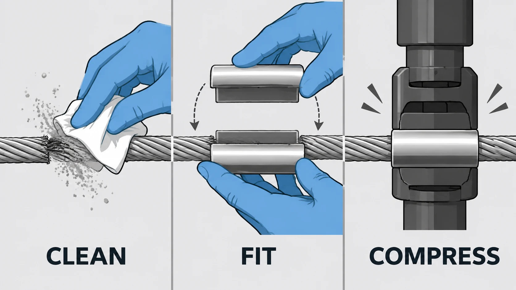
A repair sleeve is a short tubular or split component fitted over the damaged zone to bridge broken outer strands, re-establish a continuous conductive path, and leave a smooth exterior that will not snag, arc, or hold water. Depending on design it is compressed onto the conductor with a matched die set or closed around it as a split assembly. Which applies, which die, and the operation sequence come from that kit’s specification sheet and its listed tooling — no generic setting carries over from a different kit or conductor size.
The limits matter more than the description. A sleeve suits a bounded zone of outer-strand damage. It does not rebuild a steel core, correct a flattened section, or turn a long degraded length back into sound conductor. It must match the exact conductor designation, diameter, and strand lay; a kit chosen by “about the right size” will slip or bite into strands. Clean the zone, check that no sharp strand ends remain underneath, then confirm the sleeve is seated over the full marked length, its ends finished as instructed, and the assembly free of protruding edges.
Preformed Repair Rods (Patches)
Preformed repair rods are helical rods laid as a set over the damaged zone to restore the outer section and spread bending strain over a longer length than a short sleeve can. They need no compression tooling and are compact to carry, which is also why they are the most frequently misapplied repair product on a line.
A rod set is designed for one conductor diameter and one lay direction. Rods are not cut to fit, mixed between sets, reused after removal, or applied over a sleeve or a deformed section to hide it. The marked centre of the set sits over the marked centre of the damage, and each rod is seated in the order given in the kit instructions. At a fitting, the rods must be compatible with armour rods or the clamp body already installed; stacking two preformed products is a decision for the specification sheet, not for the crew. The same handling logic applies across the preformed family — the guy grip guide treats lay direction, matching, and one-time use the same way.
When a Joint Sleeve Is the Reinforcement Answer
If the damaged length is longer than a local repair can cover, remove it and install a joint sleeve, turning an unplanned repair into a planned joint. The question shifts from “how do I cover these strands” to “where am I allowed to put a joint in this span”. Joint position, how many are permitted, distance to fittings, and required documentation are project or utility rules. A joint also changes the mechanical behaviour of the span, so sag and tension are re-established per the project specification rather than left as found. Compression sequence, die selection, and electrical checks then follow the jointing procedure covered by the aluminium conductor joint guide linked above. What belongs in the repair decision is simpler: is the conductor on either side sound enough to join into, and does the resulting joint location satisfy the rules? If either answer is no, restring.
When Restringing Is the Cheaper Answer
Restringing sounds expensive, but with an outage already scheduled it is often cheaper than a repair that has to be revisited. The cases are consistent. Any core damage in a composite conductor is a replacement decision, because a surface repair cannot verify or restore the core. Damage spread over a long length, or several sites in one span, leaves the section between repairs in uncertain condition. Flattened or disturbed lay will not be brought back by a sleeve. If the span has no record of when damage occurred, or the utility’s rules require a strength assessment that cannot be completed on site, replacement is the conservative answer.
There is a practical test too. If the matching kit is not in store, the listed tooling or dies are missing, or the crew would have to substitute a component from another kit, stop the job. An improvised repair on a live asset costs more than a planned replacement. The same applies when the repair would place a joint where the specification does not permit one. The output of the inspection is then a restringing recommendation with the conductor designation and affected length attached, not a span signed off as sound.
Matching the Repair Kit to the Conductor
Every repair product is a matched component, not a consumable. The kit part number is selected from the conductor designation, measured diameter, stranding and lay direction, conductor material, and whether there is a steel core. Two conductors with similar outside diameters but different stranding are not interchangeable, and a kit for an all-aluminium conductor is not automatically suitable for a composite one. Where a line carries more than one conductor type, hold separately identified kits for each, with the designation printed on the package.
Tooling is part of the same match: die, press or hand tool, and any check gauge come from the kit’s specification sheet. Receiving them deserves the same discipline as any other line hardware — part numbers, packaging, surface condition, and accompanying documents before the kit enters the store. Our incoming inspection guide for line hardware applies as much to a small repair kit as to a pallet of clamps. Store rods and sleeves so they cannot bend, and quarantine any kit with damaged packaging or an unreadable label rather than issuing it.
Installation Sequence and Field Checks
The order of work is the same whatever product is chosen, and most errors come from combining steps to save an outage. Isolate and permit the work to site safety rules, re-inspect the damage under proper access rather than from the patrol photograph, clean and mark the zone, trial-fit the kit, then apply it. Rod order and seating, or die, compression sequence, and number of operations, follow the kit specification sheet. No figure for any of those belongs in a general article.
| Step | What to check | What to record |
|---|---|---|
| Isolation and access | Permits, earthing, safe approach per site rules | Permit reference and responsible crew |
| Re-inspection at the work position | Damage matches the report; no hidden core damage | Updated description and scaled photographs |
| Kit verification | Part number matches conductor designation; packaging sound | Kit part number and batch identification where used |
| Marking and trial fit | Damage and repair centres align; coverage is complete | Marked length per the project method, not an estimate |
| Application | Sequence, tooling, finishing per the kit specification sheet | Tool identification and procedure confirmation |
| Finished assembly | Fully seated, smooth ends, no protruding strands | Photographs of the finished repair from two angles |
| Restoring the span | Sag, tension, attachments per the project specification | Sign-off reference and scheduled follow-up |
After the Repair: Inspection, Records, and Handover
A repair is not finished when the crew comes down. The span returns to the inspection programme with a note that it has a repaired section, so the next patrol looks at that exact position. The follow-up is a comparison, not a fresh judgement: same angle, same scale, same reference points, looking for movement of the sleeve or rods, new strand damage at the ends, discoloration, or changes in the adjacent fitting. General visual patrol methods are in the overhead line fittings inspection guide; the repair record tells the inspector where to concentrate them. Any specialised survey the utility uses belongs to its own procedure and should be logged against the same span identifier.
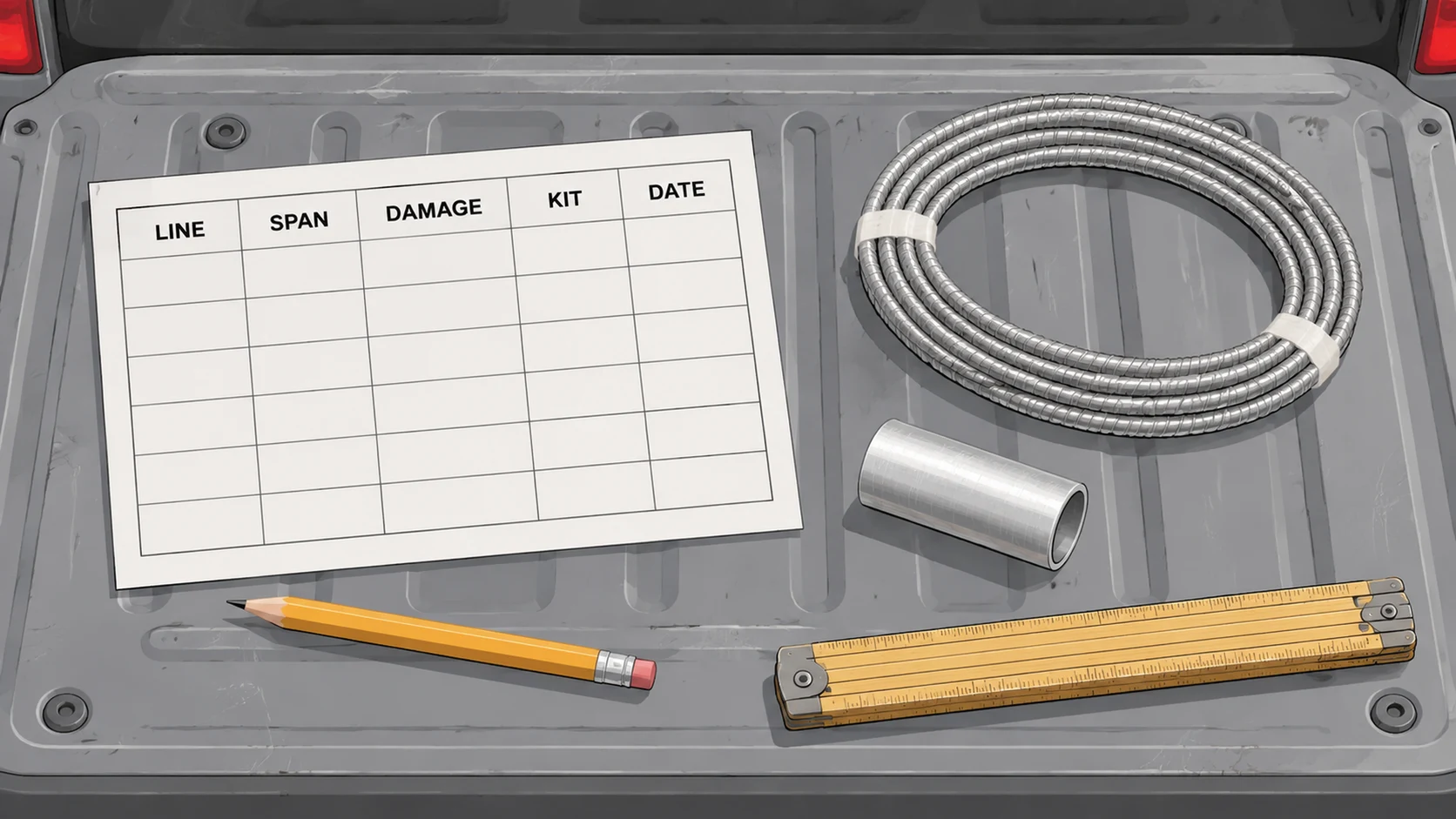
The paperwork makes the repair auditable: the original report, the disposition and why, the kit part number and tooling, the crew and date, before-and-after photographs, and the scheduled follow-up. If a joint sleeve was installed, record the joint position and its approval; if restringing was recommended, say so explicitly with the conductor designation and affected length, so the recommendation does not quietly become a repair at a shift change.
| Record field | Why it matters | Who uses it next |
|---|---|---|
| Line, span, position in span | Lets a later crew find the point without re-walking | Patrol crew and asset records |
| Original description and photographs | Baseline for judging whether the repair has worsened | Follow-up inspector |
| Disposition and the rule behind it | Shows the choice came from the specification, not the van | Maintenance engineer and auditor |
| Kit part number, tooling, installer | Makes a later product or batch question answerable | Storekeeper and maintenance engineer |
| Follow-up date and findings | Closes the loop or escalates to replacement | Next patrol crew and planner |
Procurement: Specifying Repair Kits in an RFQ
Most repair-kit orders go wrong before the kits are needed, because the enquiry says “repair sleeves, assorted sizes” instead of listing the conductor schedule. Start with the conductors in service: designation, diameter, stranding, lay direction, material, and whether they have a steel core. State which repair method is wanted for each — sleeves, rod sets, joint sleeves, or a combination — and ask the supplier to confirm the matching kit part number and listed tooling. Where utility rules require approval or documents for joints in a span, include that too. Ask how kits are identified on the package, how they are packed, and what documents accompany them: a kit that cannot be matched to a conductor designation on a night call will be misapplied. The guide to specifying overhead line fittings in an RFQ covers the wider enquiry structure, and repair kits should be specified in the same terms rather than as a small-order afterthought.
Frequently Asked Questions
Can a repair sleeve restore the full tensile strength of the conductor?
Not automatically, and that assumption should never be made on site. A sleeve restores the outer bundle and the electrical path over a bounded zone. Whether the repaired section meets the mechanical requirement is answered by the manufacturer’s data sheet for that conductor and kit, and by the utility’s maintenance rules. Where a composite conductor’s core is affected, replacement is the normal disposition.
Can preformed repair rods be removed and reused?
No. A rod set is matched to one diameter and lay direction, and its condition after removal cannot be verified to the standard of a new set. Rods are not cut down or borrowed from another set to make up a shortfall. Scrap the used set and hold a correctly identified spare for each conductor type in service.
Do we need to take the line out of service for every repair?
That is decided by site safety rules and the work method for the voltage level and access conditions, not by the repair product. The procedure here assumes the conductor has been isolated, permitted, and earthed as required. Any question about live work or minimum approach belongs in the utility’s safety documentation.
How can we tell whether a steel core is damaged?
Visible signs such as disturbed lay, flattening, birdcaging, or corrosion beneath broken strands are warnings, not proof either way. Where the report raises that possibility, the disposition comes from the conductor specification sheet and the utility’s assessment rules. Do not cover a suspected core issue with a surface repair and sign the span off as sound.
What if we have the sleeve but not the matched tooling?
Stop the job. Die, tool, and sequence are part of the kit specification, and substituting tooling from another kit invalidates the finished assembly. The correct output is a replacement or rescheduling recommendation listing the missing items, not a repair carried out with an approximate setup.
In practice, the quality of a conductor repair is decided before the van reaches the span: by the completeness of the damage report, by whether the kit on the shelf matches the conductor in service, and by whether the maintenance rules for that line are on hand. If you are assembling an enquiry for repair kits, start with the conductor schedule and the rule that defines your acceptance limits. Those two documents determine which of the three dispositions above is genuinely available to the crew, and they make the record that follows worth keeping.