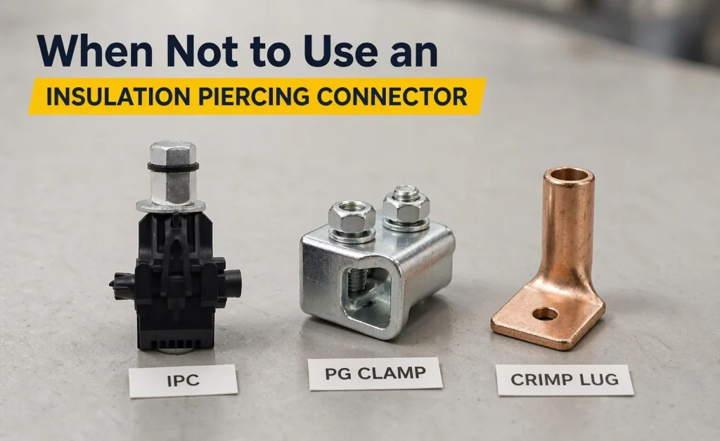
When Not to Use an Insulation Piercing Connector
Insulation piercing connectors are the most convenient fitting on a distribution van. No cable stripping, no crimping tool, one bolt to tighten, and the branch is live in under a minute. That convenience is why they end up on joints they were never intended for — a heavy branch here, a mismatched conductor there, a temporary feed that becomes permanent. The clamp holds, the lights stay on, and the failure shows up two or three summers later as a burnt body at the top of a pole.
This article is about the boundary, not the product. If you want the working principle and the internal construction, what an insulation piercing connector is covers that ground, and the type breakdown sits in IPC working principle and types. Here the question is narrower and more useful at the quotation stage: in which situations should you specify something else entirely, and what should that something else be?
What the Clamp Is Actually Asked to Do
An IPC makes a branch connection by driving hardened teeth through the insulation of both the main and the branch conductor, then clamping both under the force of a single bolt. Current flows through the teeth and the contact patch they create. The body is a polymer shell whose job is to keep moisture out and keep the live parts away from hands and tools.
Three limits follow directly from that design, and every situation in this article traces back to one of them. The contact area is small, so the current it can carry is limited relative to the conductor size. The mechanical grip comes from the same single bolt that makes the electrical contact, so it is not a tension fitting. And the connection is only as good as the insulation it pierces — a shell that has already degraded, or a cable whose insulation is not the type the clamp was designed for, undermines the whole joint.
None of this makes the product unsafe. It makes it application-specific, in the same way a wedge dead-end is not a suspension clamp.
Seven Situations Where an IPC Is the Wrong Choice
The list below is drawn from the joints that come back as failures or as awkward retrofits. Each one has a viable alternative, and the alternative is usually cheaper than the rework.
1. The branch has to carry the full load of the main
A service drop draws tens of amps. A branch feeding a second transformer, a workshop row, or a sub-feeder may draw the same current as the main itself. The IPC’s teeth and contact patch are sized for branch currents, not for a joint that has to behave like a continuous conductor. When the branch is effectively a continuation of the main, specify a connector rated for that through-current instead of stretching a branch connector. If the two conductors are the same size and the joint must carry full load, a bolted connector is the honest choice. 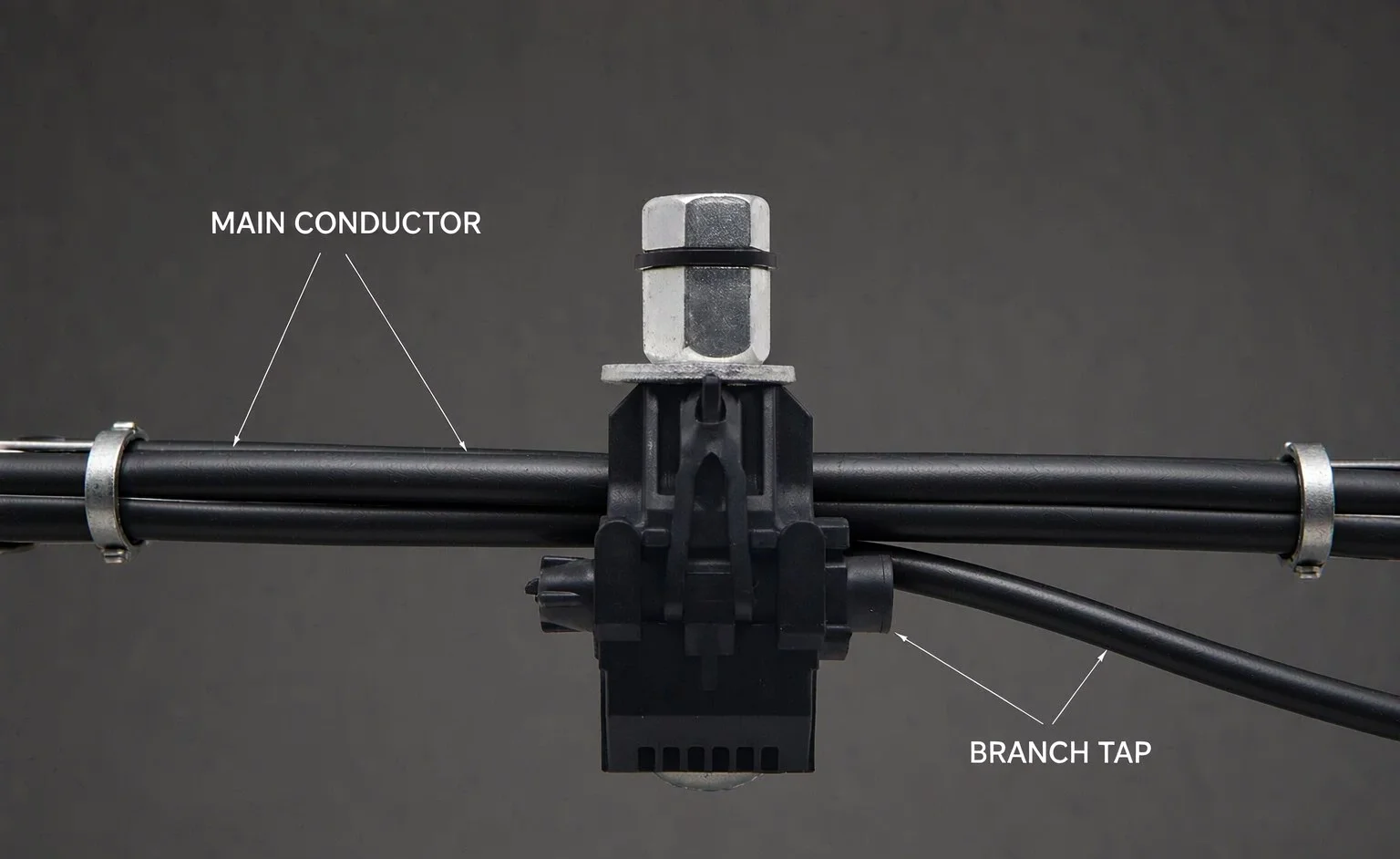
2. The cross-section difference is large
IPCs are made in size ranges, and the range assumes both conductors sit within it. A 16 mm² branch tapped onto a 150 mm² main is a mechanical problem before it is an electrical one: the clamp body cannot seat evenly on both, one set of teeth bites deep while the other barely contacts, and the bolt torque goes into deforming the body rather than loading the contact. Read the range on the datasheet as two independent limits — main range and branch range — and reject the joint if either conductor falls outside. Where the difference is unavoidable, use a connector with independent clamping per groove, such as a parallel groove clamp.
3. The connection will be opened and remade
Every re-termination of an IPC pierces the insulation again at a slightly different point. The second bite is on insulation that has already been punctured and stressed; the third is worse. On circuits where the branch is disconnected seasonally — irrigation pumps, temporary site supplies, event lighting — the clamp becomes a consumable that nobody accounts for. A bolted connector or a terminal block that can be opened without damaging the cable is the right answer for anything expected to be re-made more than once.
4. Ambient temperature or load cycling is severe
Two effects combine. Heat ages the polymer body, and load cycling works the bolted joint loose as materials expand at different rates. An IPC has no way to indicate that its bolt has relaxed; the teeth stay embedded but contact pressure falls, resistance rises, and the joint heats itself further. In hot climates, on heavily loaded feeders, or on circuits with strong daily cycling, prefer a connector whose clamping force can be checked and restored, and put the joint on the thermal inspection route.
5. The insulation is not what the clamp was designed for
IPC bodies are designed around specific insulation types — typically the XLPE or PVC of aerial bundled cable and insulated service cable. On cable with a thick, hard, or unusually soft sheath, on aged insulation that has hardened and cracked, or on cable whose insulation was repaired with tape, the teeth may not reach the conductor cleanly or may not seal afterwards. Where the cable type is unknown, identify it before choosing the fitting rather than after the joint fails. The ABC fitting set assumes the cable it was designed for.
6. The joint has to remain a test point
Some connections exist partly so that they can be measured: resistance checks, thermographic surveys, fault location. An IPC’s contact is inside a sealed body, which is exactly what you want for weather protection and exactly what you do not want when the joint must be probed. Where measurement access is a requirement, use a connector with exposed metal for the probe or a terminal arrangement that provides a test point, and note it on the inspection schedule.
7. The joint must hold mechanical tension
An IPC is a branch connector, not a dead-end. It will not hold conductor tension, and it must not be the only thing keeping a span up. If the branch leaves the main and immediately becomes a span under tension, the tension belongs in a tension clamp and the electrical connection belongs in a separate connector. Mixing the two functions into one small clamp is how branches end up on the ground after a storm.
What an Overloaded IPC Looks Like in the Field
Failure rarely arrives as a clean break. The first sign is a body that has discoloured or dulled compared with its neighbours on the same pole, because the polymer is being cooked from the inside by a contact that has lost pressure. Under a thermal camera the clamp runs hotter than the conductor either side of it — the classic signature of a joint carrying more current than its contact area wants.
Later the insulation around the entry points hardens and splits, water gets in, and the teeth begin to corrode. Corrosion products lift the contact pressure further, resistance climbs, and the joint enters the loop that ends in a burnt body or a blown branch. 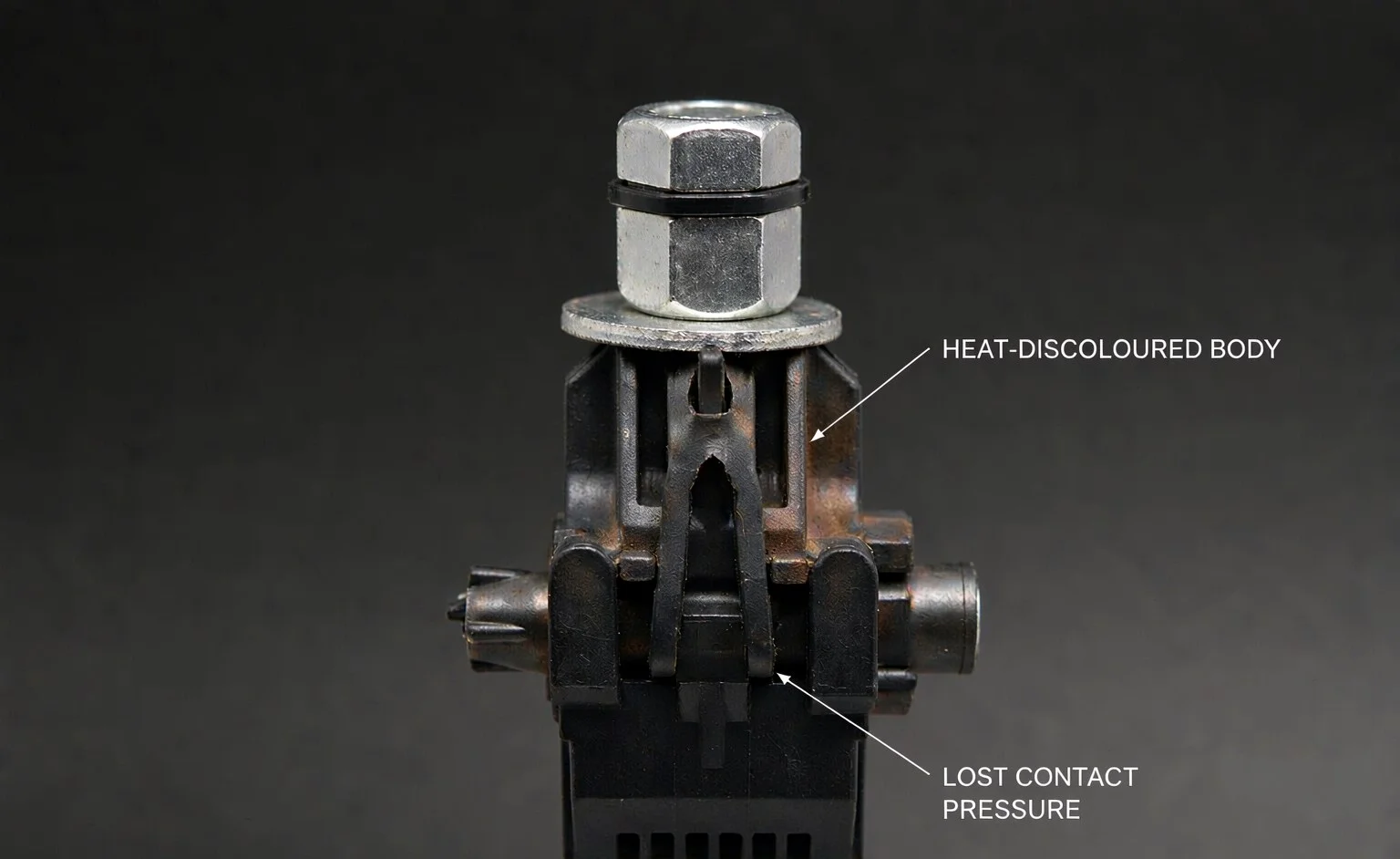 By the time the damage is visible from the ground, the joint has usually been running hot for more than one season, which is why the inspection interval matters more than the replacement decision.
Two field habits reduce the damage. Photograph each IPC joint on installation, so a later discolouration is visible against a baseline. And when a joint is replaced, cut the old body open and look at the teeth: bright, evenly embedded marks across the contact patch mean it was working as designed, while only a few shiny points mean the clamp was never seated properly on that conductor.
The Seven Cases in One Table
| Situation | Why the IPC struggles | Specify instead |
|---|---|---|
| Branch carries full main load | Contact patch sized for branch current | Bolted connector rated for through-current |
| Large cross-section mismatch | Body cannot seat on both conductors evenly | Parallel groove clamp with independent grooves |
| Frequent re-termination | Each re-make repierces stressed insulation | Bolted connector or terminal block |
| Heat and heavy load cycling | Clamping force cannot be checked or restored | Re-torqueable bolted joint on inspection route |
| Non-standard or aged insulation | Teeth may not reach conductor or reseal | Stripped-and-crimped connection in a sealed enclosure |
| Joint must stay measurable | Contact is sealed inside the body | Connector with exposed metal test surface |
| Joint carries span tension | Not a mechanical fitting | Tension clamp plus separate connector |
Read the table as a screening test, not a design document. Anything that lands in the middle column should trigger a conversation with the project engineer before the purchase order, and the joint’s rating should come from the fitting manufacturer’s data for that specific model.
The Alternatives, and What Each One Costs You
Replacing an IPC is rarely a like-for-like swap. Each alternative changes the tools on the van, the time on the pole, and what the next crew can do with the joint.
Bolted parallel groove clamp
The closest functional substitute: two conductors sit in separate grooves and are clamped by bolts, with no insulation piercing. It handles large section differences well because each groove is loaded independently, and it can be re-opened and re-torqued. The cost is that conductors must be bare at the joint, so either you are working on bare overhead line or you strip and re-insulate. The groove clamp types comparison covers the variants and where each is used. 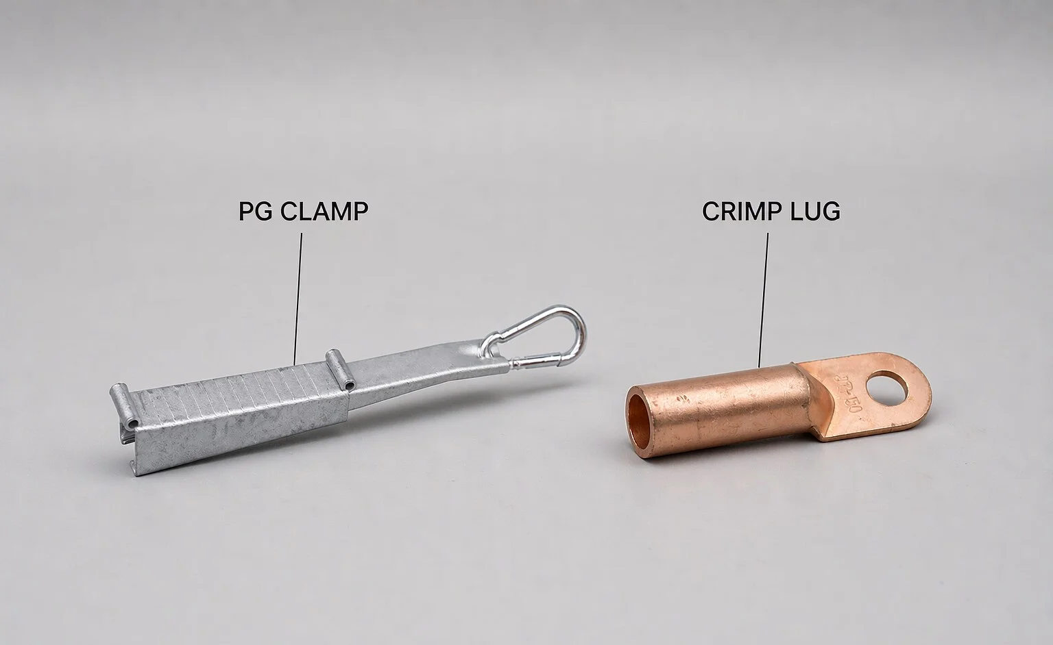
Compression lug or terminal
For a permanent branch that terminates rather than continues, a crimped terminal in an enclosure gives the lowest resistance and the most predictable long-term behaviour. It requires a crimping tool, a die matched to the lug, and correct stripping — the process is less forgiving than a bolt, which is why the crimping method matters as much as the lug. Start with cable lug types to match the lug to the conductor, and follow the sequence in the crimping guide.
Factory pre-branched assembly or junction box
Where several branches leave one point, or where the joint must be accessible and inspectable, a junction box or a factory-made pre-branched cable removes the field joint entirely. It is the most expensive option per joint and the cheapest option per failure avoided on complex LV distribution, because every connection is a bolted or clamped terminal inside a housing rather than a pierced cable in the air.
Bare conductor connector on ABC
On aerial bundled cable, some crews strip the bundle and use a bolted connector on the exposed phase conductor, then re-insulate. It is a legitimate field solution where the branch is heavy and no IPC of adequate rating exists, but it converts a one-minute job into a stripping, connecting and insulating job — plan the time and the insulation materials, not just the connector.
Comparing the Options Honestly
| Option | Tools needed | Re-openable | Through-current capability | Best fit |
|---|---|---|---|---|
| Insulation piercing connector | One wrench or socket | No — re-make repierces | Branch-level only | Light branch taps on ABC and insulated service cable |
| Bolted parallel groove clamp | Wrench or torque tool | Yes | Full conductor rating per groove | Bare overhead joints, unequal sections, re-workable connections |
| Compression lug or terminal | Crimping tool and matched die | No — cut and re-crimp | Full conductor rating | Permanent terminations inside enclosures |
| Junction box / pre-branched assembly | Wrench, cable tools | Yes, at the terminals | Full rating, multiple outlets | Several branches from one point; inspectable joints |
Two columns deserve emphasis. “Re-openable” predicts maintenance cost over twenty years, and “through-current capability” predicts whether the joint will be the hot spot on your next survey. Neither is visible on a price list, which is why connector selection on price alone tends to produce the failures this article is about.
A Decision Sequence You Can Use on the Van
Before opening the box of IPCs, four questions in order will route almost every joint correctly. First: does the branch carry the same current as the main, or materially more than a service drop? If yes, leave the IPC in the van. Second: do both conductors fall inside the datasheet’s main and branch ranges, independently? If no, move to a connector with separate grooves. Third: will this joint be opened again within its service life? If yes, choose something bolted. Fourth: does the joint have to be measured, or does it carry span tension? Either answer rules the IPC out.
If all four answers point the other way, the IPC is the right tool and nothing else on the van will beat it for speed. That balance is worth stating plainly to crews, because a rule that says “never use IPCs” gets ignored, while a rule that says “IPCs for light branch taps only” gets followed. Whatever the outcome, record the fitting model and the torque applied — that record is what makes the next inspection meaningful, as described in overhead line fitting inspection.
Where the IPC Remains the Right Answer
It is worth being explicit about the other side, because over-correcting is its own cost. For a light branch tap on aerial bundled cable, an IPC is faster, safer and more weatherproof than any stripped-and-bolted alternative, and the sealed body removes an entire class of insulation-restoration mistakes. On service connections where the branch current is modest and the cable type is known, the clamp does exactly what it was designed to do. Installation quality then decides the outcome: correct stripping of the branch end, correct conductor insertion depth, and the specified torque from the model’s datasheet — the sequence in the IPC installation guide.
The practical position is a size-and-duty limit, not a ban. Write that limit into your material specification so it survives staff changes: which cable types the IPC may be used on, up to which branch current, and which situations must escalate to a bolted or crimped connection. The RFQ specification guide shows how to state those limits so a supplier can quote against them instead of guessing.
Frequently Asked Questions
Can an IPC be used on the main feeder rather than a branch?
Physically it can be clamped on, which is exactly why the mistake happens. Electrically the clamp’s contact area is sized for branch currents, so using it to carry feeder load puts the joint at the top of the thermal survey. If the conductor pair needs to behave as a continuous feeder, use a connector rated for that through-current.
Is it acceptable to re-use an IPC after loosening it?
Not as a planned practice. The teeth have already pierced the insulation at one point; re-clamping drives them at a slightly different point on insulation that has been stressed, and the seal is no longer the one the design assumed. Where a joint must be re-made, specify a connector designed to be opened.
How can I tell whether an existing IPC joint is overloaded?
Thermography under load is the practical method: compare the clamp body temperature against the conductor a metre away on the same circuit, and against similar joints on the same feeder. A body running consistently hotter than its neighbours is carrying more current than its contact area wants, or its clamping force has relaxed. Confirm with a resistance measurement before deciding to replace.
Do IPCs work on both aluminium and copper conductors?
Only in the combinations the specific model is rated for, and the rating must come from that model’s datasheet. Aluminium-to-copper contact brings the galvanic question into the joint, and the answer is a clamp designed for that pairing, not a general-purpose branch connector used outside its stated conductor list.
The Short Version
An insulation piercing connector is a branch tap device with a small contact area, a single bolt, and a seal that depends on the insulation it pierces. Everything it should not be used for follows from those three facts: heavy branches, big section differences, joints that get re-made, hot and cycling circuits, unknown insulation, joints that must be measured, and anything that has to hold tension. Outside those cases it remains the fastest correct connection on the van.
If you are working through a bill of materials and are unsure which joints should escalate, send the conductor sizes, branch currents and cable types and we will map each connection to a fitting — the IPC range covers the branch-tap cases, and the parallel groove and lug ranges cover the rest.